

The most common stumbling block when requesting blower quotes is this: you have a flow rate and a pressure value, but none of the quotes you receive seem comparable to the other. One quote uses m³/h, while another uses Nm³/h. One uses mbar, while another uses meters of water column. For the same application, one suggests a 7.5 kW motor, while another suggests a 15 kW motor.
This confusion isn’t just a sales gimmick. In the world of blowers, two completely different families of machines and multiple flow rate definitions coexist side by side. The purpose of this guide is to help you translate the quotes you get into a common language and determine which family is right for your business.
What is a blower? The belt between the fan and the compressor
Air-moving machines are traditionally classified based on their pressure ratio—the ratio of discharge pressure to intake pressure:
- Fan: Up to 1.11
- Blower: 1.11–1.20
- Compressor: 1.20 and above
Knowing this definition is helpful, but it’s not enough on its own in the field—and understanding why makes it easier to read quotes. A positive-displacement lobe blower can easily generate 1,000 mbar of overpressure; which means 1 bar suction to 2 bar absolute discharge, or a pressure ratio of 2.0. According to the table above, this machine should be classified as a “compressor,” but the industry continues to refer to it as a blower.
This is not an inconsistency, but an established distinction: the upper limit is set for dynamic machines, and positive-displacement machines regularly exceed it. The standards also follow industry practice. ASME’s blower performance test code, PTC 13, defines a blower as a machine that delivers air at a pressure ratio of up to 3 and covers both dynamic and rotary positive-displacement types. The European safety standard EN 1012-1, on the other hand, includes rotary positive-displacement blowers with pressures up to 2 bar within its scope.
In practice, the term "blower" refers more to the machine’s function than to its pressure ratio: it is designed to move large volumes of air in a continuous flow, rather than to store air like a compressor. Keeping this distinction in mind while reviewing a quote will save you from the debate over whether “this machine is actually a compressor.”
Two families: positive displacement and dynamic
The entire choice is based on this distinction. The two families do not do the same work, and their reactions to pressure are opposite.
Lobbed (Roots) blower — positive displacement
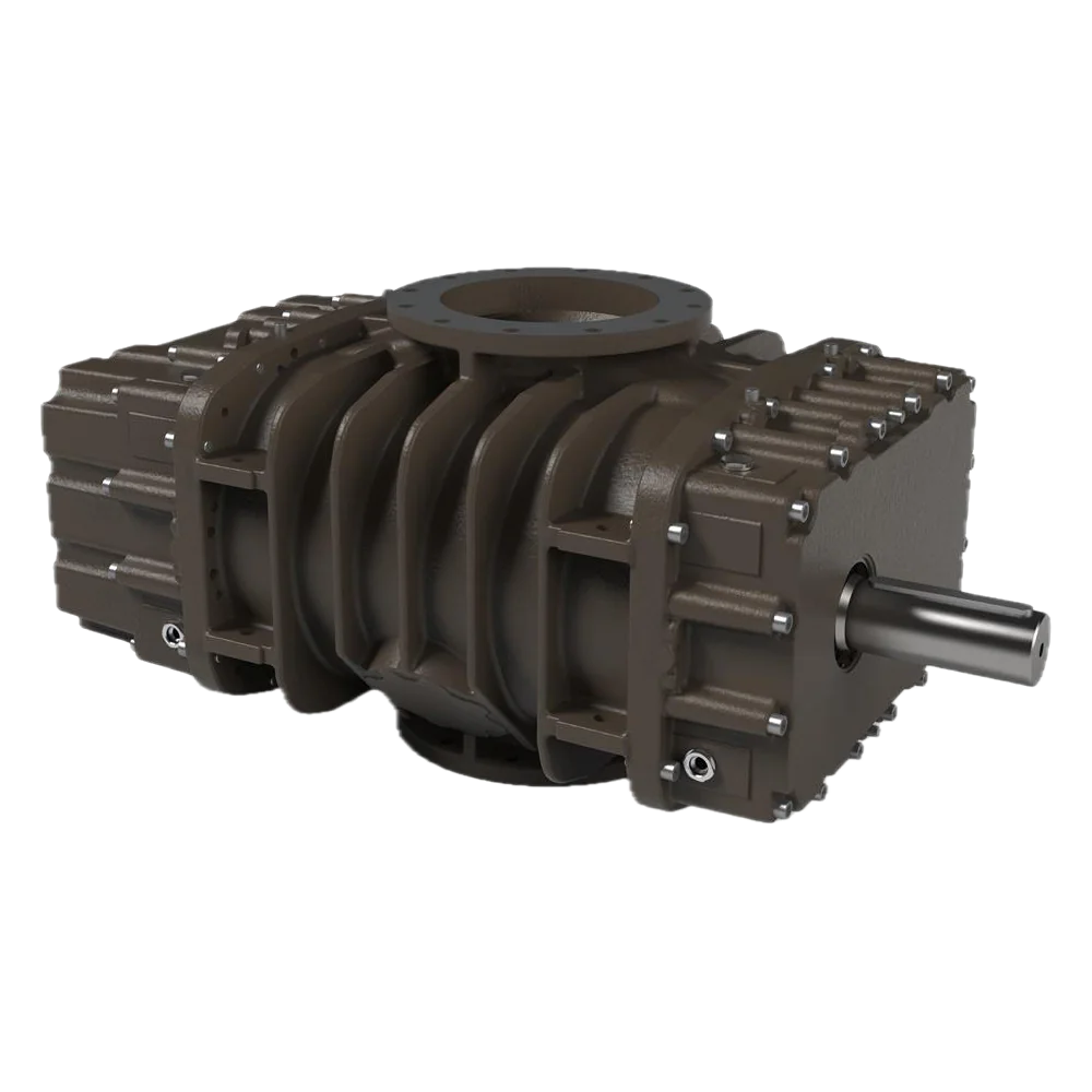
There are two rotors inside the casing that rotate in opposite directions. The rotors trap air in the pockets on the intake side and transport it to the discharge side. The most critical point to understand is this: a lobe blower does not compress the air inside it. There is no reduction in volume inside the machine. Pressure arises from the resistance encountered by the transported air at the outlet.
This has two practical consequences. First: if the speed is constant, the flow rate is also constant; even if the system pressure rises, the machine continues to move the same volume. Second: it is the system, not the machine, that determines the pressure. If you shorten the pipe, the pressure drops; if you block the diffuser, the pressure rises—the blower simply tries to push whatever is fed to it.
Since the rotors do not come into contact with each other, there is a separate pair of timing gears that keeps the rotation in sync. The rotor profile is also important: a two-lobed flat rotor produces a distinct pulse; three-lobed and helical rotors reduce this pulse and the associated noise. The terms “helical-lobed” and “three-lobed” you see in the catalog refer precisely to this difference.
Side-channel blower — dynamic
A side-channel blower is a dynamic machine: it imparts kinetic energy to the air via a rotating impeller, and this energy is converted into pressure within the casing channel. Its behavior is the opposite of that of a lobe blower—flow rate decreases as system resistance increases. When back pressure rises, the machine does not “strain”; instead, it shifts backward along its curve.
The advantage lies in maintenance. The impeller is directly connected to the shaft and does not come into contact with the casing: there are no parts subject to wear and no points requiring lubrication. In the data sheet for the side-channel blower unit we offer, this is described as “lubrication-free, virtually maintenance-free,” and the noise level ranges from 46 to 71 dBA. The number of stages (single, double, or triple-bladed) determines the pressure capacity.
Which family is suited for which job?
The following values are taken from our own product data sheets; they vary from brand to brand, but the order of magnitude reflects the family’s character.
| Loblu (Roots) | Side-channel | |
|---|---|---|
| Pressure | 1000 mbar continuous (1250 mbar peak) | 70–480 mbar |
| Vacuum | −500 mbar continuous (−750 mbar peak) | −60 – −340 mbar |
| Flow rate (casing) | 100–600 m³/h | 40 – 1,370 m³/h |
| Flow rate when pressure changes | Remains constant | Decreases |
| Lubrication | Gearbox oil required | Not required |
| Suitable for the job | High and variable back pressure | Low, stable pressure |
Rule of thumb: If the back pressure exceeds 500 mbar or fluctuates during operation, use a lobe pump; if the pressure is low and stable, use a side-channel pump. In wastewater treatment aeration, where tank level and diffuser fouling constantly fluctuate the pressure, lobe-type blowers are preferred; for low-pressure applications such as vacuum lifting, drying, and pneumatic conveying, side-channel blowers are both quiet and maintenance-free.
Reading the flow rate correctly: m³/h or Nm³/h?
This is where the most costly mistake is made when comparing quotes. The volume of a gas varies significantly with temperature and pressure, so a gas flow rate is meaningless unless the reference conditions under which it was measured are specified.
- m³/h (actual volume): the volume actually moved by the machine under actual operating conditions at the inlet. This value is generally specified in blower catalogs because the machine’s airflow volume is physically constant.
- Nm³/h (normal volume): Volume normalized to conditions of 0 °C, 101.325 kPa, and 0% humidity in accordance with DIN 1343.
- Sm³/h (standard volume): 15 °C and 101.325 kPa, as specified in ISO 2533 and ISO 13443. IUPAC uses 0 °C / 100 kPa, while NIST uses 20 °C / 101.325 kPa.
In other words, "Nm³/h" and "Sm³/h" are not the same thing, and the result depends on which organization’s definition is used. The process side typically specifies requirements in terms of mass (such as kilograms of oxygen in wastewater treatment) and uses Nm³/h; blower catalogs, however, use m³/h. Making a selection without converting between the two can lead to choosing a machine that is too small, especially in hot climates and at high altitudes.
Practical tip: When requesting a quote, specify the unit of measurement for the flow rate, as well as the facility’s altitude and the design air temperature. To move the same mass of air at 40 °C, a larger volume must be moved compared to 0 °C.
Pressure difference and temperature increase: this is the real limit
The pressure limit listed in the catalog for a lobe blower is not an arbitrary number; it is a thermal limit. As the pressure differential increases, so does the heat generated by the machine. As the rotors heat up, they expand; beyond a certain point, the rotor comes into contact with the casing, causing the machine to seize and sustain damage. This is the failure observed under excessive pressure differentials—it is not caused by oil leakage or bearing failure, but directly by thermal expansion.
For this reason, the data sheet lists two separate values: the maximum continuous operating pressure and the peak pressure. For an example casing, these values are 1000 mbar and 1250 mbar on the pressure side, and −500 mbar and −750 mbar on the vacuum side. The instantaneous value indicates the tolerable range during startup or brief blockages; it cannot be used as an operating point.
We also need to be realistic about efficiency: In Roots-type machines, peak efficiency is around 70%, and it decreases as the machine moves away from this peak. Selecting a machine based on the highest pressure listed in the catalog means operating it at the worst point on the efficiency curve.
Calculating the pressure in wastewater treatment aeration
The most common application for blowers is activated sludge aeration, and the majority of the required pressure comes from a single factor: the water head above the diffuser. The physics here are straightforward—a 1-meter water column corresponds to 98.1 mbar of back pressure.
The total pressure requirement is the sum of the following items:
- Diffuser immersion depth × 98.1 mbar/m. If the diffuser is at a depth of 4 m, this value is 392 mbar.
- The diffuser’s own pressure loss. This varies depending on the type and age of the diffuser; it is taken from the data sheet and should not be estimated. A fouled diffuser will increase this value over time.
- Pipeline and fitting losses. Calculated based on line length, diameter, and number of elbows.
- Suction filter and silencer losses. These values are taken from the data sheet; they increase as the filter becomes clogged.
Key point: Items 2, 3, and 4 increase over time. If you select the blower based solely on the conditions on the first day, the machine will exceed its maximum continuous pressure when the diffuser becomes dirty. This factor is taken into account during selection.
The flow rate, on the other hand, is derived from the oxygen demand. The oxygen transfer performance of aeration systems is measured in clean water in accordance with EN 12255-15 (standard oxygen transfer rate, SOTR); the value obtained in actual wastewater is lower than this. Therefore, rather than directly matching the air flow rate derived from the process calculation to the catalog, the reference conditions must be verified—the distinction between m³/h and Nm³/h discussed in the previous section comes into play precisely here.
Roughly controlling engine power
You can use a simple calculation to check whether the motor power specified in the proposal is reasonable. The power delivered to the air is the product of the flow rate and the pressure difference; for shaft power, this is divided by the efficiency.
For a flow rate of 600 m³/h and a pressure difference of 500 mbar: 600 m³/h = 0.167 m³/s and 500 mbar = 50,000 Pa. Air power: 0.167 × 50,000 ≈ 8.3 kW. With an approximate efficiency of 70%, shaft power ≈ 11.9 kW. When belt and motor losses are factored in, this task requires a 15 kW motor.
This isn’t a design calculation; it’s an order-of-magnitude check: the actual selection is made using the manufacturer’s selection program, which also takes the temperature rise into account. But if you receive a proposal recommending 7.5 kW for the same job, this factor will show you where to look for answers.
The same machine in a vacuum: booster
The technical data sheet for a lobe blower lists vacuum values in addition to pressure values; for example, the casing maintains a constant vacuum of −500 mbar. This is due to the machine’s symmetrical operation: if you connect the suction port to a sealed chamber, the same machine will generate a vacuum.
In industrial vacuum applications, this is used not as a standalone machine but as a booster—it is installed upstream of the main vacuum pump and reduces the pressure the system can achieve while increasing the pumping speed. In our vacuum pump selection guide, we discuss which main pumps the lobe booster is compatible with, along with liquid ring vacuum pumps and oil-sealed rotary vane vacuum pumps.
There’s a distinction here that’s often overlooked: a blower is not a source of compressed air. Equipment such as air-operated double-diaphragm pumps requires 4–7 bar of compressed air; a blower does not generate this pressure. Attempting to use a blower instead of a compressor is the most common infrastructure mistake made when selecting an AODD pump.
Auxiliary equipment and safety
A lobe blower is not sold as a bare casing; the surrounding equipment determines the machine's service life.
- Intake filter. Rotor tolerances are very tight; any solid particles that enter will scratch the casing. When the filter becomes dirty, pressure loss increases, so the differential pressure is monitored.
- Safety valve. A positive-displacement machine continues to pump into a blocked discharge line; pressure rises unchecked. EN 1012-1 requires protection against excessive pressure in this family of pumps and refers to ISO 4126-1 for safety valves. This valve is not optional.
- Check valve. Prevents system pressure from causing the machine to reverse during downtime.
- Silencer. The pulsating fluid of a lobe pump generates both noise and pipe vibration.
- Flexible coupling. It prevents vibration from being transmitted to the piping.
An additional layer is required in explosive atmospheres. The machines in our ATEX blower series are equipped with explosion-proof motors and feature the appropriate markings; for example, the marking for a specific model is II 1/2G Ex h IIA T3 Ga/Gb and II 2D Ex h IIIA T200 °C Db. Before purchasing, verify that this marking is compatible with your zone and gas group—the presence of a certificate alone is not sufficient.
Energy: Compare the "wire-to-air" offer
Blowers operate year-round in most facilities, so the purchase price is a small portion of the total cost. However, catalog efficiency ratings may not be comparable: one manufacturer may list only the efficiency of the casing and shaft, while another may list the efficiency of the entire package, including the motor and drive.
ASME PTC 13 (2018) was developed to address this issue: it compares the air output of the entire unit—including the motor, drive, gear or belt, filter, and cooling system—with the electricity it draws from the grid. This is what the term “wire-to-air” refers to, and it applies to all types of blowers, regardless of the technology used. ISO 1217 is also used for acceptance testing of positive-displacement machines.
Adding a single sentence to the specifications would make the comparison fair: performance values will be provided on a package-by-package basis in accordance with ASME PTC 13 or ISO 1217.
Symptom → cause → initial examination
| Symptom | Possible cause | Initial Check |
|---|---|---|
| The casing is overheating; the paint is burning | Pressure differential exceeds the maximum continuous value | Install a pressure gauge on the discharge line; check for dirt buildup in the diffuser and filter |
| Struggles during startup, then recovers | The line remains under pressure during downtime | Check valve and blow-off system |
| Metal grinding noise, sudden stoppage of operation | Rotor has come into contact with the casing due to thermal expansion | Do not operate the machine; check ΔP and rotor clearance |
| Flow rate has decreased over time, pressure remains the same | Rotor clearances have increased due to wear (internal leakage) | Speed check; compare with design flow rate |
| Pressure has increased, flow rate has decreased (side channels) | Normal behavior — the machine is drifting along the dynamic curve | Compare the operating point to the curve |
| Oil consumption has increased; the air smells of oil | Gearbox seal is worn out | Oil level and seal; is the oil type suitable for the application as shown on the data sheet? |
| Noise and pipe vibration have increased | The silencer is worn out or the flexible coupling has stiffened | Muffler packing; condition of the compensator |
| The motor is overheating | Back pressure is above design specifications or the motor is undersized | Current measurement; order-of-magnitude check using ΔP × flow rate |
Election Checklist
- Flow rate and unit: m³/h or Nm³/h? Is the reference condition specified?
- Altitude and design air temperature: These affect the intake density and must be specified in the proposal.
- Pressure drop: Were the components calculated separately (immersion + diffuser + pipe + filter)?
- Contamination margin: Will the machine continuously exceed the limit as the diffuser and filter age?
- Pressure stability: Does it vary during operation? If so, check the positive displacement side.
- Maximum: continuous or instantaneous? Is the operating point below the continuous value?
- Auxiliary equipment: Are a safety valve, check valve, silencer, filter, and flexible connection included in the quote?
- Safety and compliance: EN 1012-1; is the marking compliant with the zone in an explosive atmosphere?
- Energy: Is performance specified on a package basis (ASME PTC 13 / ISO 1217)?
- Noise: Has the dBA value in the data sheet been compared to the site limit?
- Maintenance: Have the oil change interval, belt tension, and access to spare parts been clarified?
Frequently Asked Questions
What is the difference between a blower and a compressor?
A compressor is designed to compress and store air and deliver it at high pressure (typically several bar). A blower moves a much larger volume of air at lower pressure in a continuous flow. Traditional classification is based on a pressure ratio of 1.20, but positive-displacement blowers exceed this limit; the functional distinction is more reliable.
Doesn't a lobe blower actually compress the air?
There is no volume reduction inside the machine; air is transported through the chambers. The pressure increase results from the resistance encountered at the outlet. For this reason, the same machine produces different pressures in different systems—and can raise the pressure to dangerous levels in a blocked line, which is why a safety valve is required.
What is the maximum pressure a single-stage lobe blower can produce?
It varies depending on the casing size; a sample casing in our data sheets provides 1000 mbar continuous and 1250 mbar peak pressure. It is not the pressure itself that sets the limit, but the temperature increase caused by the pressure difference: the machine is damaged when the rotor expands and comes into contact with the casing. If higher pressure is required, staging or a different technology is considered.
How much does the difference between Nm³/h and m³/h affect the selection?
This has a significant effect. Nm³ is the volume reduced to 0 °C and 101.325 kPa (DIN 1343); however, the actual air at the machine’s intake is warm and稀薄. To move the same mass, a larger volume of air must be drawn in when the air is warm. Selecting a unit based on a flow rate value without specifying the reference conditions carries the risk of undersizing the unit.
What pressure should I set for the aeration system?
The water head above the diffuser is the dominant factor: 98.1 mbar per meter. Added to this are the diffuser’s own head loss, pipeline head loss, and suction filter/silencer head loss. Since these factors increase as the diffuser and filter become clogged, a margin is built into the selection; however, a machine selected based on first-day conditions may exceed its continuous operating limit after one year.
Can I use the blower as an air source for a diaphragm pump?
You cannot use it. Air-operated double-diaphragm pumps typically operate with 4–7 bar of compressed air from the utility supply; a blower does not produce this pressure. A blower is a high-volume, low-pressure machine, while a compressor is a low-volume, high-pressure machine. The two are not interchangeable.
Side-channel blower or lobe blower?
The choice depends on the pressure and its stability. If the pressure is low and stable, a side-channel blower is quiet, requires no lubrication, and is virtually maintenance-free. If the pressure is high or fluctuates during operation, a lobe blower is required, because its flow rate remains independent of the back pressure.
Summary
The selection of a blower can be boiled down to two questions: How high is the back pressure, and how much does it vary? If the answer is “high and variable,” a positive-displacement lobe blower is the right choice; if it is “low and stable,” a side-channel blower is the right choice. Everything else—the reference condition for flow rate, the temperature rise limit, the contamination margin, and the safety valve—constitutes the engineering details surrounding this decision.
If you provide us with your flow rate, pressure requirements, and the facility’s altitude along with the design temperature, we can work together to determine the appropriate product family and casing size. You can review our lobed blowers and lobe boosters, side-channel blowers, and ATEX blower series, or get in touch with us for technical support.