


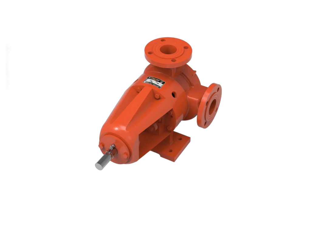
A pump designed for water is often ineffective when dealing with molasses or resin. As viscosity increases, the logic behind pump selection changes entirely: volume takes precedence over speed, and priming capacity over efficiency. This guide explains the rules for selecting the right technology for viscous liquids.
The guide addresses, in order, whether the viscosity of your fluid is constant, where the centrifugal pump actually stops, how to select the speed, and typical field malfunctions. If you’re experiencing a problem on an operational line, you can refer to the troubleshooting table.
First, define viscosity correctly
Two units are used and mixed together:
The key point is this: viscosity changes dramatically with temperature. An oil that has a viscosity of 100 cSt at 50 °C can exceed 1,000 cSt at 10 °C. Selecting a pump based on an operating temperature of 50 °C and commissioning it on a cold winter morning with cold product will result in the motor failing to start or the shaft bending.
Rule: Size the pump based on the operating viscosity, and select the drive and motor based on the viscosity during commissioning.
Viscosity is not a single number for every product
In liquids such as oil, molasses, and glycerin, viscosity depends solely on temperature; it does not change no matter how much you stir them. These are called Newtonian liquids, and the cSt values listed in catalogs assume this behavior.
However, many products used in the food, cosmetics, paint, and slurry industries do not behave this way. In these products, viscosity varies depending on how quickly the fluid shears (shear rate):
Practical takeaway: If your product is not Newtonian, you should ask the manufacturer not only for the "viscosity" but also at what shear rate it was measured. Otherwise, the values provided by two different laboratories for the same product could differ significantly, and your choice will depend on that.
Where does a centrifugal pump end?
A centrifugal pump imparts velocity to a fluid and converts that velocity into pressure. As viscosity increases:
In practice, centrifugal pumps become uneconomical above the 200–500 cSt range. Beyond this limit, positive displacement pumps are used: these pumps mechanically displace a fixed volume per revolution; as viscosity increases, internal leakage decreases, so their efficiency does not decline—it actually improves.
Viscosity correction in a centrifuge: the curve cannot be read as is
Centrifugal pump catalogs specify performance based on water. When pumping a viscous fluid, the same pump produces lower flow rate and lower head, and draws more power. This loss is calculated using correction factors, not estimates.
The Hydraulic Institute’s ANSI/HI 9.6.7 guideline outlines the method for this calculation: it defines how to predict the performance of rotodynamic pumps in Newtonian fluids that are more viscous than water. Its scope is limited to fluids with kinematic viscosities between 1 cSt and 4,000 cSt that exhibit Newtonian behavior—this limit of the guide also defines the boundary of the centrifugal pump’s “calculable” range.
Two practical conclusions follow from this. First: if a proposal recommends a centrifugal pump for a viscous fluid, the corrected flow rate, head, and power values must be requested; selection based solely on the performance curve will be insufficient in the field. Second: the motor power is selected based on the corrected power, because power consumption is the parameter that increases most rapidly with viscosity.
Positive displacement pump families
Internal gear pumps
The volume between an outer gear (rotor) and the smaller gear (idler) inside it expands and contracts as it rotates, thereby creating a pumping action. This is the most common industrial solution for viscous fluids.
In our range of internal gear pumps, the KIP and KIPK series are available in sizes ranging from ⅜" to 4".
Helical gear pumps
Because the teeth are helical (angled), engagement occurs gradually. The result: lower pulsation, quieter operation, and smoother flow. This is advantageous for high-viscosity applications and continuous operation.
In our line of helical gear pumps, the KHP series is available in sizes ranging from ½" to 6".
Lobe Pumps
The two lobes rotate using synchronous gears without coming into contact with each other. Because the rotors do not touch each other, they are ideal for hygienic applications; they can be cleaned in place using CIP/SIP.
Our KLP series lobe pumps are available in 1½", 2", and 2½" sizes within the lobe pump category.
Progressing cavity pumps (helical rotor / PCP)
A helical metal rotor rotates inside an elastomer stator. The enclosed cavities formed between them transport the fluid by moving it from the suction side to the discharge side.
Our progressing cavity pump lineup includes the AH, BAH, DK, ECO, FL, KR, MN, PH, RK, and SH series.
Comparison Table
| Standard | Internal / helical gear | Lobe | Progressing cavity pump (PCP) |
|---|---|---|---|
| Viscosity capacity | High | High | Very high |
| Solids Tolerance | Low (sensitive to abrasives) | Good (large particles) | Very good (fibrous/abrasive) |
| Shear sensitivity | Low shear | Lowest shear | Low shear |
| Hygiene / CIP | Limited | Very suitable | Suitable models available |
| Pressure capacity | High | Medium | High (multi-stage) |
| Dry running | Tolerates short periods | Limited | Absolutely not |
| Consumable/wear part | Gear, bushing | Rotor, seal | Stator (replaced regularly) |
Downshifting: the most important design rule
In positive displacement pumps, capacity is directly proportional to speed; however, as viscosity increases, the pump speed must be reduced. The reason is simple: it takes time for a viscous fluid to fill the pump’s clearances. If the speed remains high, the clearances will not fill completely—flow rate decreases, noise and vibration increase, and cavitation begins at the suction side.
For this reason, manufacturer data sheets do not list capacity on its own, but rather in the format "… cSt @ … rpm." The notation "500 cSt @ 1450 rpm" means full performance up to a maximum of 500 cSt at that speed.
| Viscosity | Typical recommended speed range |
|---|---|
| 1 – 100 cSt | Nominal speed (1,450 rpm) |
| 100–1,000 cSt | Approximately 70–100% of the nominal speed |
| 1,000 – 10,000 cSt | Approximately 40–70% of the rated speed |
| Above 10,000 cSt | 25–40% of the rated speed or less |
This range is a general guideline; the exact value should be taken from the manufacturer’s curve for the selected model. In practice, speed reduction is achieved using a gear-driven drive or a variable frequency drive. A larger pump that delivers the same flow rate at a lower speed will last longer and operate more quietly than a smaller pump that is overworked at high speeds.
An essential component of a positive displacement pump: the safety valve
A centrifugal pump balances its pressure against a closed valve and stops. A positive displacement pump does not stop—it continues to displace the same volume with each revolution, and the pressure rises until something breaks. That is why every positive displacement pump line is equipped with a safety (relief) valve.
Suction line: becomes critical in terms of viscosity
Since friction loss increases in direct proportion to viscosity, the design of the suction line is critical in a viscous fluid:
For the calculation method, please refer to our NPSH and cavitation guide.
Hot products and heating
Products such as asphalt, paraffin, chocolate, and resin solidify at room temperature. In these services:
From Symptom to Cause: Diagnosis via the Viscous Line
| Symptom | Possible cause | Initial Check |
|---|---|---|
| Engine won’t start, thermal cutout | Start-up torque in a cold engine | Viscosity during commissioning; wait for the motor to warm up |
| Flow rate below catalog specifications | RPM is too high for the viscosity—gaps aren’t priming | Reduce speed (gearbox/variable frequency drive) |
| Noise, vibration, or irregular flow at the suction | Suction line is narrow/long; NPSH is insufficient | Suction diameter and length; NPSH calculation |
| Power consumption is higher than expected | Viscosity is higher than calculated or the line has cooled down | Actual operating temperature; line insulation/heating |
| Pump does not rotate during downtime | Product has solidified inside the pump | Jacket temperature; downtime flushing procedure |
| Sudden loss of performance in the progressing cavity pump, burning smell | Stator burned out due to dry running | Dry running protection; level switch |
| Pressure is rising; line/valve is overloaded | Discharge line is clogged; safety valve is missing or misadjusted | Safety valve adjustment and relief path |
| Product degradation, phase separation | Shear damage — high speed or incorrect type | Reduce the speed; switch to a low-shear type (lobe) |
| Rapid wear in the gear pump | Abrasive solids in the product | Solid analysis; switch to a lobe or progressing cavity pump |
Election Checklist
Frequently Asked Questions
Up to how many cSt can a centrifugal pump be used?
In practice, it becomes uneconomical above the 200–500 cSt range. Even below this range, performance deviates from the water curve; corrected flow rate, head, and power values in accordance with ANSI/HI 9.6.7 should be requested. The scope of this guide covers Newtonian fluids in the 1–4,000 cSt range.
Why is it necessary to reduce the RPM when viscosity increases?
It takes time for the dense fluid to fill the pump cavities. If the speed remains high, the cavities will not fill completely: flow rate decreases, noise and vibration increase, and cavitation begins at the suction side. A large pump that delivers the same flow rate at low speed has a longer service life than a small pump that is overworked at high speed.
Gear pump, lobe pump, or progressing cavity pump?
As a general rule: clean, high-pressure, viscous transfer → gear pump; hygienic, particulate, and shear-sensitive products → lobe pump; very high viscosity, fibrous, and abrasive slurry → progressing cavity pump. If there is a risk of dry running, avoid using a progressing cavity pump or require protective measures.
My product thins out when stirred—what viscosity should I use?
Your product is not Newtonian. Instead of a single number, you need a viscosity value that specifies the shear rate at which it was measured. Additionally, since the product will be much thicker during the first startup after a long period of downtime, the drive should be selected with this in mind.
Is a safety valve really necessary?
Yes. The positive displacement pump continues to press against the closed valve; the pressure rises until something breaks. The valve setting must be verified with the actual product, and care must be taken to ensure that the drain line does not freeze in heated lines.
If you share your product and operational data with us, we can work together to determine the appropriate type, size, and cycle. Explore our gear pumps and lobe pumps as well as our progressing cavity pumps, or get in touch.