

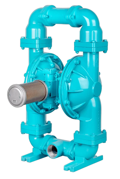
An air-operated double-diaphragm pump is a positive displacement pump type that operates using compressed air and does not have an electric motor. It is used in a very wide range of applications, from corrosive chemicals to thick slurries, and from food products to paint. However, selections based solely on the “maximum flow rate” figure listed in catalogs often result in insufficient capacity or unexpectedly high air bills in the field.
In this guide, we discuss the four criteria that determine the selection of an AODD: duty point (flow rate + pressure), actual air consumption, suction lift, and diaphragm material. We then address ATEX compliance, food contact, and field failures. The example values are taken from the data sheets of the diaphragm pump series we offer. If you are experiencing issues with a pump that is currently in operation, you can proceed directly to the troubleshooting table.
How does an AODD pump work?
The air valve in the center of the pump directs compressed air to the two diaphragm chambers in turn. As the air pressure pushes one diaphragm forward, the opposite diaphragm is pulled back by the common shaft: one side presses while the other side draws in. Four check valves (one intake and one discharge valve in each chamber) ensure unidirectional flow. The pilot valve reverses the air flow at the end of the stroke to maintain the cycle.
This simple architecture has three important practical consequences:
These three features do not make the AODD the “best pump for every application”; they make it the pump for demanding and irregular service conditions. In a continuous, constant-flow, clean transfer line, a centrifugal pump operates more cost-effectively and with higher efficiency. Where the AODD excels is in applications involving corrosive, viscous, or solid-laden fluids, or where the line frequently runs dry.
Flow Rate and Pressure: The 1:1 Rule
The most critical feature of an AODD pump is this: the maximum fluid pressure it can deliver is equal to the air pressure you supply. If your air line delivers 6 bar, the pump will deliver approximately 6 bar; if it delivers 8.4 bar, the pump will deliver 8.4 bar. In other words, the air pressure determines the fluid pressure.
The data sheet for the AP 20 metallic diaphragm pump we offer clearly illustrates this relationship: operating air pressure 0–8.4 bar, head 0–84 mss (meters of water column). Since 84 mss ≈ 8.4 bar, the two values correspond exactly.
The catch here is this: the maximum flow rate listed in the catalog is measured at zero discharge pressure (free flow). For the AP 20, this value is 565 liters per minute. However, if there is 4 bar of back pressure in your line, the actual flow rate will be significantly lower than this figure. The correct selection is made using the manufacturer’s performance curve: you plot your target flow rate against your line’s actual back pressure and determine which air pressure corresponds to that point.
A common mistake when calculating back pressure is to consider only the static head. The actual back pressure is the sum of three components: static head + friction loss in the pipe and equipment + the pressure at the end of the line (if you are pumping into a closed tank, filter, or nozzle). In viscous products, friction loss is often greater than the static head.
Rule of thumb: Do not operate the pump continuously at maximum capacity. An AODD operating at 60–80% of its rated flow rate consumes less air and significantly extends the diaphragm’s service life. The mechanical reason for this is simple: flow rate is directly dependent on the number of cycles per minute, and the diaphragm’s lifespan is depleted by the number of cycles. Running the pump at a lower flow rate is the most cost-effective way to extend the diaphragm’s service life.
Air consumption: an overlooked operating cost
The purchase price of an AODD pump is low; the main cost is compressed air. Compressed air is one of the most expensive forms of energy in a factory and is the factor most often overlooked when selecting an AODD pump.
Again, from the AP 20 data sheet: air consumption 33–169 m³/h, air connection 3/4". Let’s look at the upper limit—169 m³/h is approximately 2.8 m³/min of free air, and a 20 kW-class compressor is required to meet this demand. Since the same pump delivers a maximum of 565 liters per minute (≈34 m³/h) of liquid, the air-to-liquid volume ratio is roughly 5:1.
To understand what this ratio means, you can calculate the operating cost using data from your own facility. The formula consists of three steps and requires no estimates:
This calculation yields a surprising result at most facilities: the annual air cost of a continuously operating AODD can exceed the pump’s purchase price. The conclusion here is not to avoid AODDs—rather, it is to make an informed choice, knowing that centrifugal pumps or positive displacement pumps are more energy-efficient for continuous, clean, and constant-flow applications.
So when making your choice, ask yourself this question: Can my current compressor supply this pump along with other loads? Insufficient air supply means the pump will slow down and the target flow rate will never be reached. A significant portion of the malfunctions reported in the field as “the pump is running weakly” are actually caused by problems with the air line, not the pump itself.
Measures to Reduce Air Consumption
Suction lift: it depends on whether the surface is dry or wet
AODD pumps are self-priming; they can be installed above the liquid level. However, there are two different suction values, and they are often confused:
In the AP 20 data sheet, this value is given as 6–8 m. It is safe to design the system based on the dry suction value: do not assume that the suction line will be primed every time the pump starts up.
As viscosity increases, suction capacity decreases. For high-viscosity fluids, positioning the pump below the liquid level (flooded suction) is the best solution. For information on the relationship between suction-side losses and NPSH, please refer to our NPSH and cavitation guide.
One detail is often overlooked: dry-suction capability depends on the type of check valve. Ball valves seat under their own weight; when the pump is mounted horizontally or the ball is made of a very lightweight material, the sealing weakens and the pump struggles to prime during dry suction. In lines where suction lift is critical, the valve type and installation orientation must be confirmed with the manufacturer.
Diaphragm material: the most critical decision
Most AODD failures are caused by the wrong diaphragm material. Two criteria are evaluated together during selection: chemical resistance and flex life. The material with the highest chemical resistance is not necessarily the one with the longest mechanical life—this trade-off is at the heart of the selection process.
| Materials | Temperature range | Strengths | What to Avoid | Elongation life |
|---|---|---|---|---|
| Santoprene (TPE) | −23 … +120 °C | General-purpose; acids/bases, wastewater | Aromatic and chlorinated solvents | Very good |
| PTFE (Teflon) | +4 … +100 °C | Broadest chemical resistance; concentrated acids, solvents | — | Poor (rigid structure) |
| EPDM | −50 … +100 °C | Hot water, bases, ketones | Oils and hydrocarbons | Good |
| NBR (Buna-N) | −12 … +82 °C | Petroleum products, oils, fuels | Strong acids, ketones | Good |
| FKM (Viton®) | −29 … +120 °C | High temperature, aromatic/chlorinated hydrocarbons, aggressive acids | Hot concentrated bases | Low |
| Neoprene | −18 … +93 °C | Economical, general-purpose | Strong oxidizers | Very good |
The most commonly used solution in practice is a two-piece diaphragm: the surface facing the fluid is PTFE, with Santoprene or FKM behind it as a backing. This combines the chemical resistance of PTFE with the fatigue life of the elastomer. If both chemical resistance and a long service life are required, this is generally the right choice.
The AP 20 data sheet lists the following options for internal materials: Neoprene, Buna-N, Teflon, Viton, Santoprene, and EPDM; for the casing, the options are aluminum, cast iron, and stainless steel (316). You should base your material selection not only on the diaphragm but also on all parts that come into contact with the fluid (casing, manifold, ball, seating surface, O-ring)—our chemical compatibility guide, which covers this topic in detail, explains this chain of components.
Why and how does the diaphragm tear?
There are three distinct mechanisms that cause the diaphragm to wear out, and their symptoms vary:
When the diaphragm ruptures, liquid passes into the air side and is expelled through the exhaust. This poses a serious risk when handling hazardous liquids: the exhaust line must be routed to a safe location, preferably a collection container. Diaphragm failure sensors that provide early warning of a tear are also available; their use should not be optional in applications involving toxic and flammable substances.
Casing material and solids transfer
The choice of casing is both a chemical and a mechanical decision:
One of the AODD’s standout capabilities is its ability to handle solid particles: for the AP 20, this value is 6 mm. This offers a distinct advantage over centrifugal pumps in applications involving slurry and sediment. However, abrasive solids cause rapid wear on the diaphragm and balls; for such applications, the heavy-duty (APH) series should be considered.
There is a limit to the ability to handle solids, and this limit is not particle size but rather the settling rate. Heavy particles settle in the suction manifold while the pump is stopped and prevent the valve from seating during the next startup. In slurry applications, flushing the pump with clean water at the end of a shift is much less expensive than replacing the diaphragm.
ATEX and use in explosive atmospheres
The fact that the AODD does not have an electric motor is a major advantage in explosive atmospheres—but it does not automatically make the pump ATEX-compliant. In the European Union, this equipment falls under Directive 2014/34/EU (ATEX); in Turkey, the equivalent is the “Regulation on Equipment and Protective Systems Intended for Use in Potentially Explosive Atmospheres,” which has been harmonized with the same directive. For an AODD to be used within this scope, the pump itself must be marked as compliant.
In practice, three factors are decisive:
Food, Beverages, and Pharmaceuticals: Hygiene Services
AODD pumps are widely used in the food and beverage industry: they handle products gently (low shear force), handle viscous products, can draw from the bottom of tanks, and operate without electricity. However, having a “stainless steel casing” does not necessarily mean the pump is hygienic. There are three key requirements for equipment that comes into contact with food:
Pulse (pulsation) and installation errors
AODD flow is inherently pulsating. This pulsation causes the line to vibrate, distorts the flowmeter reading, and wears out equipment such as filters and membranes. The solution is to install a pulsation dampener in the discharge line. In applications involving precise dosing or filtration, this is not an option—it is a necessity.
For the damper to function properly, the pre-charge pressure must be adjusted according to the line pressure; a damper installed with its factory settings often does not produce the expected effect. The damper should also be mounted as close to the pump as possible.
Other common mistakes encountered on the field:
From Symptom to Cause: Rapid Troubleshooting
| Symptom | Possible cause | Initial Check |
|---|---|---|
| The pump is not running at all | No air, regulator closed, pilot valve installed | Line pressure, regulator, air valve |
| It’s running but not pumping fluid | Failed to prime, air leak at suction, valve not seating | Suction connection sealing, ball and seat |
| Flow rate is low, pump is slow | Insufficient air pressure/flow rate, line diameter too small | Actual pressure at the pump inlet (measure while running) |
| Liquid is coming out of the discharge | Diaphragm is torn | Stop the pump; divert the discharge to a safe location |
| Icing in the discharge line; the pump is stopping | Moist air + expansion cooling | Air dryer, silencer cleaning |
| Pump is knocking, line is vibrating | Pulsation; no damper or damper not adjusted | Dampener pre-charge pressure |
| Diaphragm wears out frequently | High cycle count, incorrect material, or abrasive solids | Duty point, material compatibility, solid particle size |
| Liquid backflow | Check valve ball is worn or fouled | Ball/seat assembly, line flushing |
Election Checklist
Frequently Asked Questions
Can an AODD pump run dry?
Yes. Since there are no sliding mechanical seals or bearings that require lubrication, dry running does not damage the pump. This makes the AODD pump more advantageous than a magnetic drive pump for applications such as tank drainage and services where the line is frequently empty.
How do you adjust the flow rate?
There are two ways to do this: by reducing the air pressure at the regulator or by throttling the valve in the discharge line. Throttling on the suction side is not the correct approach. The most efficient method is to reduce the air pressure to the actual requirement; this also reduces air consumption.
Is it harmful to run the engine with the valve closed?
No — The AODD valve stalls at the closed position and maintains pressure in equilibrium with atmospheric pressure. This is a fundamental difference from a centrifugal pump and eliminates the need for a safety valve in most applications. However, the line must be rated to withstand a static pressure equal to the air pressure.
What should you do if fluid is leaking from the exhaust?
The diaphragm has ruptured. The pump must be shut down immediately, and the diaphragm assembly (both sides together) must be replaced. When handling hazardous liquids, the discharge line must have been routed to a safe location in advance.
Can it print viscous products?
Yes, an AODD pump is much more suitable for viscous fluids than a centrifugal pump. However, as viscosity increases, suction capacity and flow rate decrease; the pump should be selected one size larger, the suction line should be kept short and wide, and, if possible, a flooded suction should be used. For very high viscosities, gear pumps or progressing cavity pumps should be considered.
Is it more expensive to run than an electric pump?
For continuous, constant-flow applications, yes—compressed air is a more expensive energy carrier than electricity. AODD valves excel in intermittent operation, applications with a risk of dry running, and environments involving solids, corrosive chemicals, and ATEX zones. The choice should be based on the application profile, not the purchase price.
You can explore the AP, APX, and APH series, as well as the Seko Duotek models, in our diaphragm pumps category, which offers options with metal, plastic, hygienic, and heavy-duty casings; You can get in touch with us by providing the name of your fluid, flow rate and back pressure values, your air source, and any ATEX or hygiene requirements, if applicable.