

Selecting a vacuum pump boils down to two questions: what pressure do I need to achieve, and how long will it take—or what gas flow rate is required—to reach that pressure? Choices made without determining these two values will either fail to meet the target entirely or result in a system that is larger and more expensive than necessary.
In this guide, we compare three main technologies: liquid (water) ring, oil-sealed rotary vane, and lobe booster (Roots). The example values are taken from the data sheets of the products we present.
Next, we’ll discuss how to measure leakage, why the pipe diameter in the vacuum line can be a more critical factor than the vacuum pump, and common field malfunctions. If you’re experiencing issues with a system that’s currently operational, you can refer to the troubleshooting chart.
First, the units: absolute pressure and vacuum scales
Pressure in a vacuum is expressed in absolute terms: one atmosphere ≈ 1013 mbar; a perfect vacuum = 0 mbar. "The lower the pressure, the deeper the vacuum."
| Range | Pressure range (absolute) | Typical technology |
|---|---|---|
| Rough vacuum | 1013 – 1 mbar | Liquid ring, rotary vane, dry screw |
| Medium vacuum | 1 – 10⁻³ mbar | Two-stage vane, Roots booster combination |
| High vacuum | Below 10⁻³ mbar | Diffusion / turbomolecular (with fore pump) |
The vast majority of industrial applications fall within the low- and medium-vacuum range.
Unit Confusion and the "% Vacuum" Fallacy
Vacuum is a field where different units are used depending on the industry, and this is where the most common mistakes are made when comparing quotes. Practical conversions:
| Unit | Equivalent | Where it is used |
|---|---|---|
| 1013 mbar | 1 atm (sea level) | Reference point |
| 1 mbar | 100 Pa = 0.75 Torr | The common language of industrial vacuum |
| 1 Torr | ≈ 1.333 mbar (1 mmHg) | Laboratory, thermal processing |
| 1 Pa | 0.01 mbar | SI unit, in standards |
| 1 inHg | ≈ 33.86 mbar | Equipment labels from the U.S. |
The real pitfall is the phrase "% vacuum": this is not an absolute pressure, but a relative ratio to atmospheric pressure, and it varies with altitude. While “90% vacuum” corresponds to an absolute pressure of approximately 101 mbar at sea level, the same percentage represents a different absolute pressure at an altitude of 1,000 m. Always use absolute pressure (mbar or Pa) when drafting specifications and getting a quote.
Ensuring that the performance values in the catalog are comparable also requires a standardized measurement method. The ISO 21360 series defines this: it standardizes three methods for measuring volumetric flow rate (constant gas flow, orifice, and discharge methods) as well as measurements of final pressure, compression ratio, and critical inlet pressure; a separate section for positive displacement pumps (such as rotary vane and lobe pumps) also covers steam tolerance and power consumption measurements. If you can place the curves of two different manufacturers side by side, this standard is the basis for that comparison.
Liquid ring vacuum pumps
An impeller mounted eccentrically inside the casing rotates; the fluid inside (usually water) adheres to the casing wall due to centrifugal force, forming a ring of fluid. The volume between the impeller blades and this ring expands and contracts as it rotates, creating suction and pressure.
Its greatest strength: It is tolerant of the presence of vapor, moisture, dust, and liquid droplets in the gas being pumped. Wet processes that degrade the oil in oil-lubricated pumps do not cause problems here. Furthermore, compression is nearly isothermal; the temperature increase is minimal, which provides a safety advantage when handling flammable or explosive gases.
Critical limit: service water temperature
The lowest pressure a liquid-ring pump can achieve is limited by the vapor pressure of the fluid at that temperature. Water cannot drop below its own vapor pressure—no matter how hard the pump works.
| Service water temperature | Vapor pressure of water ≈ lowest achievable pressure |
|---|---|
| 15 °C | ≈ 17 mbar |
| 20 °C | ≈ 23 mbar |
| 30 °C | ≈ 42 mbar |
| 40 °C | ≈ 74 mbar |
Manufacturers typically provide performance curves for service water at 15 °C. During the summer months, when the feed water temperature rises to 30 °C, both the achievable vacuum decreases and the capacity drops—because the pump uses part of its volume to transport its own water vapor.
This is the most common cause of complaints on-site that “the pump isn’t pumping as well as it used to,” and the solution is not to replace the pump, but to cool the service water (using a heat exchanger, cooling tower, or by increasing the fresh water flow rate).
If the suction pressure approaches the vapor pressure of water too closely, bubbles form and collapse in the ring: cavitation. Operating a liquid-ring pump near its limit for an extended period causes noise, vibration, and impeller erosion. For the physics behind this phenomenon, please refer to our guide on cavitation.
Our lineup of liquid ring vacuum pumps includes single- and two-stage units, monoblock models, the ECO-SYS smart liquid ring unit, and water- and oil-circulating systems.
Oil-sealed rotary vane vacuum pumps
The vanes in the slots of the eccentric rotor press against the casing due to centrifugal force; the resulting reduction in cell volume compresses the gas. Oil provides sealing, lubrication, and cooling. Because the oil film seals even very fine gaps, much deeper vacuums can be achieved than with liquid-ring pumps.
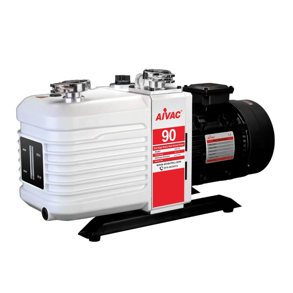
The data sheet for the ARV-90 two-stage model in our line of oil-sealed vacuum pumps illustrates this difference:
Within the same group, the VP Mini series (VP 115–VP 2200) covers smaller capacities, while the PVP series covers higher flow rates.
What is a gas ballast used for?
The greatest weakness of oil-sealed pumps is water vapor. The vapor that is drawn in condenses during compression and mixes with the oil; the oil becomes emulsified, compromising lubrication and sealing, causing the pump to lose vacuum and suffer wear.
The gas ballast draws a controlled amount of clean air into the cell during the compression phase. This ensures that the partial pressure of the vapor remains below the condensation point, and the vapor is expelled without condensing or mixing with the oil.
The trade-off is clearly evident in the ARV-90 data: when the gas ballast is on, the ultimate vacuum decreases from the order of 10⁻⁴ to 4 × 10⁻³ mbar. In other words, in a humid process, you activate the gas ballast and sacrifice some vacuum depth. This is not a malfunction; it is a designed trade-off.
Practical tip: After a wet process, running the pump for 20–30 minutes with the gas ballast on and the suction line closed (oil-cleaning cycle) significantly extends the oil’s service life.
Lobe (Roots) blower and vacuum booster
Two rotors, each with non-contacting lobes, rotate in opposite directions via synchronous gears and displace the gas volumetrically. No oil or liquid enters the compression chamber—it operates in a dry running mode.
Key point: The Roots booster cannot discharge directly into the atmosphere on its own. Its compression ratio is low; it absolutely requires a backing pump. Its function is to “multiply” the backing pump’s speed: it engages below a certain pressure, increasing the pumping speed many times over.
Typical combinations:
Our range of lobe blowers and vacuum booster units includes the HLB helical lobe (HLB1210 – HLB2768) and TLB triple-lobe (TLB4048 – TLB4099) series, as well as vacuum booster units.
When do dry types come into play?
In addition to these three main technologies, dry screw pumps—which contain no oil or fluid in the compression chamber—have also become widespread. They differ from lobe boosters in that they can discharge directly to atmospheric pressure on their own and can achieve deep pressures in the rough vacuum range.
The reason for choosing them is generally operational rather than technical: they are selected in applications where the risk of oil contamination is unacceptable (pharmaceuticals, food, electronics) or where the management of waste oil and service water is undesirable. On the other hand, the initial investment is high, and the rotor clearances must be kept clean in dusty or sticky processes. They do not offer the tolerance of a liquid-sealed bearing in wet processes or the cost advantage of an oil-lubricated bearing; the choice is made based on the process’s contamination profile.
Comparison Table
| Criterion | Liquid-ring | Oil-sealed rotary vane | Lobe (Roots) booster |
|---|---|---|---|
| Achievable pressure | Limited by service water temperature (≈17–74 mbar) | Very low (single-stage ~10⁻², two-stage ~10⁻³–10⁻⁴ mbar) | Does not operate independently; improves the performance of the fore pump |
| Steam/moisture tolerance | Very high | Low (requires gas ballast) | High (dry running) |
| Dust/droplet tolerance | High | Low (filter required) | Medium |
| Risk of oil contamination | None | Present (oil mist filter) | None in the compression zone |
| Maintenance | Service water management | Regular oil and filter changes | Gearbox oil, low maintenance |
| Typical applications | Paper, food, wastewater, steam processes | Packaging, CNC clamping, heat treatment, laboratory | Large-volume + deep-vacuum systems |
Calculating capacity
Vacuum pump capacity is a volumetric value expressed in m³/h and varies depending on pressure; it is not based on a single figure in the catalog, but rather on the pumping speed curve.
Approximate discharge time:
t ≈ (V ÷ S) × ln(p₁ ÷ p₂)
t: duration (hours) · V: volume (m³) · S: average pumping rate (m³/h) · p₁: initial pressure, p₂: target pressure.
Example: We want to depressurize a 2 m³ tank from 1013 mbar to 100 mbar; the average pumping rate is 90 m³/h.
ln(1013 ÷ 100) = ln(10.13) ≈ 2.32
t ≈ (2 ÷ 90) × 2.32 ≈ 0.0515 hours ≈ 3.1 minutes.
This calculation is for drainage only. In actual systems, leakage and the gas/steam load from the process are added; in steady-state operation, the pump primarily handles this load. In a line with poor sealing, increasing the pump size is not the solution—the leakage must be eliminated first.
Don't guess where the leak is: pressure rise test
Leaks in a vacuum system can be quantified with a simple measurement. After the system has been brought down to the target pressure, the pump valve is closed, and the rate at which the pressure rises over time is recorded:
Leakage flow rate ≈ (Δp × V) ÷ Δt
, where Δp is the pressure increase, V is the system volume, and Δt is the elapsed time. The result is expressed in a unit such as mbar·lt/s and is directly used in pump selection.
Two points are important when reading the test results. If the pressure rises linearly and continuously, there is a genuine leak. If the rise is rapid at first but then levels off at a certain value, the cause is not a leak but moisture and gas being released from internal surfaces (outgassing)—in this case, the system must be dried out rather than inspecting the gaskets. Any intervention that fails to distinguish between the two is a waste of time.
Pipe diameter: a silent restriction that chokes the pump
In a vacuum, the pipe is a much more critical factor than in liquid lines. As pressure drops, the gas’s ability to flow through the pipe (conductivity) decreases rapidly; a long, narrow line can effectively cut the pump’s capacity in half—not just on paper, but in practice.
The effective pumping rate detected by the system is calculated based on the pump speed (S) and the line conductivity (C):
Efficiency = (S × C) ÷ (S + C)
The practical implication of this relationship is clear: if the line’s flow capacity is less than the pump’s flow rate, increasing the pump’s capacity yields almost no benefit. If you connect a 100 m³/h pump to a line with a flow capacity of 50 m³/h, the system will deliver 33 m³/h; increasing the pump capacity to 200 m³/h will only raise this value to 40 m³/h. The real benefit comes from shortening the pipe and increasing its diameter.
Quick Match Based on the App
| Application | Appropriate technology |
|---|---|
| Food packaging (vacuum packaging) | Greasy rotating pallet |
| Vacuum clamping on a CNC/machining center | Oily pallet or dry type |
| Processes involving steam and moisture, vacuum drying | Liquid ring (plus Roots if necessary) |
| Wastewater and slurry dewatering | Liquid-ring |
| Vacuum thermal treatment, metallurgy | Two-stage vane + Roots booster |
| Distillation / solvent recovery | Liquid-ring (with suitable service fluid) or Roots combination |
| Laboratory, low-volume | VP Mini-class small vane |
From Symptom to Cause: Diagnosing Vacuum System Issues
| Symptom | Possible cause | Initial Check |
|---|---|---|
| Cannot reach target vacuum at all | Leak, incorrect technology, or insufficient line conductivity | Pressure rise test; pipe diameter and length |
| Vacuum level drops in the liquid ring during summer | Service water has heated up — vapor pressure limit | Inlet water temperature and flow rate; heat exchanger/cooling |
| Milky-white oil in the oil-lubricated pump | Water vapor has mixed with the oil | Open the gas ballast; oil purge cycle; oil change |
| Final vacuum in the oil pump has been compromised | Oil is contaminated or the exhaust filter is clogged | Oil condition, oil mist filter back pressure |
| Pump is overheating, smoke from the exhaust | High exhaust back pressure (clogged filter / long line) | Filter and exhaust line |
| Roots unit is overheating | Commissioned due to very high pressure differential | Start-up pressure and pre-pump capacity |
| Noise, vibration, and erosion on the impeller in the liquid ring | Cavitation — suction pressure is very close to vapor pressure | Cavitation guide; cavitation protection line |
| Capacity has decreased over time | Scale/sediment (liquid-ring) or filter clogging | Service water quality, suction filter |
| Discharge time is much longer than calculated | Leakage load or steam release from the process | Pressure rise test; is the rise linear? |
Points to Consider During Maintenance
Frequently Asked Questions
Why can't a liquid-ring pump drop below a certain pressure?
This is because the limiting factor is not the pump itself, but the vapor pressure of the coolant at that temperature. While the vapor pressure drops to around 17 mbar with water at 15 °C, it rises to around 74 mbar when the water is heated to 40 °C. The solution is not to replace the pump, but to cool the service water.
Is it okay if I leave the gas ballast on all the time?
In wet processes, yes, it is even necessary; the trade-off is that the ultimate vacuum is slightly reduced. In applications requiring dry and deep vacuum, however, it is shut off. This is not a malfunction, but a designed trade-off.
If I make the pump bigger, will it create a vacuum faster?
Not always. If the line’s flow capacity is less than the pump’s speed, the effective speed is limited by the line, and increasing the pump’s capacity yields almost no benefit. First, you need to shorten the pipe and increase its diameter, and seal any leaks.
Can Roots Booster be used on its own?
No. Because its compression ratio is low, it cannot discharge directly into the atmosphere; it must be connected to a fore-pump. Its function is to come online when the pressure falls below a certain level, thereby increasing the pumping rate.
Where should the vacuum pump exhaust be directed?
In oil-lubricated pumps, the exhaust carries oil mist; it should not be released into the environment. An oil mist filter must be used, and the exhaust line should be short and wide—a long, narrow exhaust line creates back pressure and causes the pump to overheat. If solvents or hazardous gases are being extracted from the process, the exhaust must be directed to a safe collection/disposal line.
If you provide us with your target pressure, the volume to be evacuated, and the moisture/dust conditions in your process, we can work together to determine the appropriate technology and capacity. Explore our oil-sealed, water-sealed, and rotary vane vacuum systems, or get in touch with us.