

There are two different people looking for a "hot oil pump," and neither of them is looking for the same machine. One is looking for a circulation pump to continuously circulate oil between the heater and the consumer; the other is looking for a transfer pump to pump oil from the tank into the system, fill the expansion tank, or transport a heated, viscous product.
These two applications require different flow rates, different pressures, and different pump families. If you don’t specify which one you want when getting a quote, the responses you receive will not be consistent. This guide first covers the physics of the system, then this distinction, and finally the selection criteria based on temperature.
Why is a hot oil system chosen over a steam system?
To heat water above 200 °C, you need to pressurize it; at 300 °C, the vapor pressure rises to tens of bar. Organic heat transfer oils, on the other hand, reach high temperatures under conditions close to atmospheric pressure. As a result, the boiler room, piping, and safety equipment are much lighter.
The cost, however, is the fluid itself: oil is not an inexhaustible substance; it is a substance that ages. The entire engineering of the system is designed to slow down this aging process—and the pump’s role here is more central than most people realize.
Mass temperature and film temperature: the system's breaking point
A fluid flowing through a pipe does not have a single temperature. Two separate reference points are used in heat transfer:
- Bulk temperature: the equilibrium temperature that would be reached if the fluid in the cross-section were adiabatically mixed. This is the reference used to evaluate the fluid’s properties—the value shown on your thermometer is close to this.
- Film temperature: the temperature of the thin layer in contact with the heater surface. It is always higher than the bulk temperature.
The key point is this: oil degrades at the film temperature, not the bulk temperature. Even when the panel reads 280 °C, the layer on the wall of the heating tube may be much hotter, and degradation begins there. That is why the data sheet lists two separate limits: maximum bulk temperature and maximum film temperature. Confusing the two means destroying the oil while believing the system is still within safe limits.
This is where the pump’s function comes into play. The difference between the film temperature and the bulk temperature depends on how well the fluid is mixed at the heater surface. As the flow slows down or stops, this difference increases. The pump does more than just carry the oil; it sweeps across the heater surface, keeping the film temperature close to the bulk temperature. A drop in flow rate is not merely a comfort issue—it directly affects the fluid’s service life.
Two operating rules follow directly from this: the pump is activated before the heater, and it continues to run for a while after the heater is turned off. Both are the result of the same physical principle—the oil film left on a hot surface degrades rapidly when there is no flow.
Oil degradation: What does thermal cracking do?
Heat transfer oils break down when exposed to sufficiently high temperatures, and the extent of degradation increases with both temperature and duration of exposure. This is a well-documented fact: ASTM D6743 is a test method for measuring the thermal stability of unused organic heat transfer oils and applies to fluids with a maximum operating temperature ranging from 260 °C to 454 °C. The method determines the mass percentages of high- and low-boiling-point components, gaseous decomposition products, and the non-volatile fraction in the oil subjected to thermal stress.
In the field, this is observed in both of these ways:
- Light fractions (components with low boiling points): lower the oil’s flash point and increase the tendency for evaporation in the expansion tank and cavitation in the pump.
- Heavy fractions and carbon: accumulate as deposits on the heater surface. This buildup reduces heat transfer, requiring a higher film temperature for the same outlet temperature, which in turn accelerates degradation—a self-perpetuating cycle.
This is a guide for the evaluation of hydrocarbon-based heat transfer fluids in accordance with ASTM D5372 for oil selection and monitoring. Practical implication: The system’s oil is analyzed periodically; a drop in flash point and an increase in solid content are indicators that must be detected before the oil reaches the pump.
Two different pumps, two different jobs
This is the most practical section of the guide. Two machines with the same name:
Circulation pump — centrifugal pump
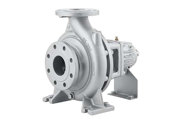
It continuously circulates hot oil between the heater and the consumer (press, reactor, dryer, jacketed boiler). Characteristics: high flow rate, medium head, steady-state operation, high temperature. The oil has low viscosity at this temperature, so a centrifugal pump is the appropriate choice.
The ECO SKY air-cooled hot oil pumps we offer are designed specifically for this application; the data sheet reflects the scale of the operation: operating temperature up to +350 °C, flow rates up to 550 m³/h, head up to 105 m, discharge flanges ranging from DN 32 to DN 150, and a casing pressure of 10 bar (16 bar). The definition of the pumpable fluid is also clear: heat transfer oils and low-viscosity industrial oils that do not contain abrasive particles.
In milder operating conditions, a standard pump may be sufficient: the series in our standard pump lineup, which complies with the TS EN ISO 2858 standard, operates between −10 °C and +175 °C with a casing pressure of 16 bar (25 bar). The difference between 175 °C and 350 °C requires a complete redesign of the casing and bearing assembly—simply calling it a “centrifugal pump” is not enough.
Transfer and feed pump — positive displacement
Pumping oil from the storage tank into the system, topping off the expansion tank, transporting a heated, viscous product (resin, bitumen, wax, heavy oil), or providing a metered feed are all different tasks. Characteristics: low flow rate, high pressure, high viscosity, self-priming. A centrifugal pump will not work here; a positive displacement pump is required.
The performance data for our gear pump and lobe pump series define the limits of this application: 20–200 °C operating temperature, 100–25,000 cP viscosity range, 1–14 bar pressure, and a flow rate ranging from 0.175 m³/h to 20 m³/h, depending on the model. Flow rate is given in liters per revolution (L/rev)—a hallmark of positive displacement: if you know the speed, you know the flow rate.
The heating cap listed in the accessories section illustrates the primary purpose of this product line: to keep a product that solidifies or becomes excessively thick in the environment warm inside the pump. Forcing a frozen casing during startup is the most common cause of failure in gear pumps; the heating cap solves this problem. Helical gear models also feature a bypass accessory—this is a safety feature, not a convenience, because in a positive-displacement pump, pressure rises unchecked when the line is blocked.
We discuss in detail how viscosity determines the selection of a pump type in our guide to transferring viscous fluids. API 676 is used as the reference for the specifications of rotary positive-displacement pumps.
Selection Chart by Temperature
The following values are taken from our product data sheets. Temperature is, by itself, the most significant parameter limiting selection.
| Temperature Limit | Family | Typical job | Caution |
|---|---|---|---|
| +175 °C | TS EN ISO 2858 standard centrifuge | Mild circulation, hot water/oil | 16 bar (25 bar) casing |
| +200 °C | Gear / helical gear / lobe | Transfer, feeding, viscous products | 100–25,000 cP; heating cover |
| +200 °C | Sliding-vane (sealless) | Constant low flow rate, high pressure | Up to 2,000 cP; 13 bar |
| +315 °C | Magnetically driven centrifugal pump (API 685) | Circulation where leakage is not acceptable | Sealless; Plan 11 internal lubrication |
| +350 °C | ECO SKY air-cooled centrifugal pump | Hot oil circulation | 550 m³/h, 105 m, 10 bar (16 bar) |
The key takeaway from the table: 200 °C is a threshold. This is the upper limit for positive-displacement transfer pumps. If you need to operate above 200 °C, you’ll need to switch to centrifugal pumps, at which point cooling and sealing become separate engineering challenges.
Why air-cooled?
In a pump operating at 350 °C, the bearing assembly and sealing element cannot withstand the fluid temperature; a thermal barrier is installed between them. There are two options: cooling with a water jacket or with air.
Air cooling is preferred in hot oil applications because a water circuit brings its own set of problems: scaling, the risk of freezing, sudden temperature shock when the water supply is cut off, and a separate auxiliary system that requires maintenance. In an air-cooled design, the finned intermediate section on the shaft dissipates heat; there is no additional circuit, so the potential for failure is minimal. The ECO SKY data sheet states that the cooling method is simply “air-cooled”—this means you do not need to plan for a water line in your installation.
The rear-accessible design mentioned in the same data sheet is also a requirement specific to hot oil systems: the hot oil pipeline is typically welded and insulated. Being able to remove the bearing assembly, shaft, and impeller without disconnecting the snail from the system determines whether maintenance will be a one-day job or a week-long installation project.
Sealing: With or sealless mechanical seal?
Hot oil is one of the most challenging fluids for a mechanical seal to handle. When leaking oil drips onto a hot surface, it poses a fire hazard; furthermore, high temperatures shorten the service life of elastomers. There are two approaches:
- Mechanical seal + flushing plan. Cooled or clean fluid is directed onto the seal surface. These designs are standardized under API 682; the specification refers to them by design number. For our gear pumps and lobe pumps, sealing options include soft packing, mechanical seals, and felt.
- Sealless (magnetically driven). The shaft never leaves the casing, so there is no path for leakage to the outside. The API 685-compliant series in our magnetic pump line operates between −100 °C and +315 °C, with a system pressure of 16 bar (up to 200 bar and higher for special applications) and features internal lubrication per Plan 11. We have detailed the engineering of the sealless solution in our guide to magnetic drive pumps.
The selection of gaskets and elastomers is also limited by temperature; you can find information on the temperature limits for each material in our material selection guide.
Cold start: the most common pitfall
Hot oil is more fluid than water at 300 °C. The same oil is a thick liquid at 20 °C. The pump is selected based on the operating temperature, but the machine must start up while cold.
This has two consequences. First is engine power: the viscosity of cold oil increases the starting torque, so an engine rated for warm-up conditions may struggle during startup. Second is the behavior of the centrifugal pump: efficiency decreases at high viscosity, and the pump fails to deliver the expected flow rate. For this reason, in hot-oil systems, the initial heating is performed in stages, and the system is brought up to full flow only after the oil has warmed up.
Then there’s the suction side. The hot fluid operates at a pressure close to its vapor pressure; as the temperature rises, the available suction lift (NPSHa) decreases, and the system approaches the cavitation threshold. This risk increases further as the light fractions in the oil rise. We covered how to calculate the suction line in our NPSH and Cavitation Guide using calculated examples—hot service is the scenario where the vapor pressure term in that guide has the most severe impact.
Safety and Regulations
Facilities that use organic heat transfer fluids are subject to a separate safety framework. DIN 4754-1 covers facilities where organic heat transfer fluids are heated below or above their boiling point at atmospheric pressure; it specifies safety requirements for design, installation, operation, and maintenance, as well as test methods, and serves to ensure compliance with the safety objectives of pressure equipment regulations.
Three factors that directly influence pump selection:
- Flow protection. The heater must shut down if the flow is interrupted. This means installing a flow switch or differential pressure monitoring around the pump.
- Leak management. Hot oil leaks pose a fire hazard; the selection of mechanical seals and the drain system are designed accordingly.
- Expansion and drainage. Oil expands when heated; an expansion tank and a safety line are part of the system, and the pump’s discharge side is designed accordingly.
Flange compatibility is also specified in the technical specifications: In the ECO SKY series, the suction and discharge flanges comply with TS EN 1092-2 / PN 16, while models with stainless steel casings comply with TS EN 1092-1 / PN 16.
Symptom → cause → initial examination
| Symptom | Possible cause | Initial check |
|---|---|---|
| The oil’s flash point has dropped; evaporation in the tank | Thermal degradation — light fractions have formed | Oil analysis; is the film temperature limit being exceeded? |
| The heater is consuming more fuel for the same outlet temperature | Carbon deposits on the heater surface | Circulation flow rate; is the pump delivering the rated flow rate on the data sheet? |
| Pump is noisy, flow rate is erratic (hot operating conditions) | Cavitation — vapor pressure has exceeded the NPSHa | Suction line and tank level; light fractions in the oil |
| The motor is straining during startup and overheating | Cold oil viscosity has increased the starting torque | Gradual heating; is a heating cap necessary? |
| Leakage from the mechanical seal, soot on the hot surface | Mechanical seals are thermally fatigued or flushing is insufficient | Flushing plan (API 682); sealless option |
| Bearing temperature is rising | Cooling zone is blocked or airflow is restricted | Cleaning of the vane-type intercooler; ambient ventilation |
| Gear pump won’t start; shaft isn’t turning | Product in the casing has cooled and solidified | Is the heating cover engaged during downtime? Drain before downtime |
| Pressure is rising unchecked (PD pump) | Discharge line is closed; bypass is missing or clogged | Bypass/safety valve; line valve position |
Election Checklist
- What kind of application? Circulation or transfer/feed? The answer determines the pump family.
- Have the maximum mass temperature and maximum film temperature been specified separately?
- Hot-run viscosity and cold-start viscosity—were both provided?
- Were the flow rate and head calculated based on the hot-run conditions?
- Was NPSHa calculated using the vapor pressure of the hot fluid?
- Cooling: Is air cooling sufficient, or is there a water line in the system?
- Sealing: Is it a mechanical seal with a flushing plan, or is it sealless? Is leakage tolerated?
- Maintenance access: Is a rear-accessible design required (welded/insulated line)?
- Are the casing pressure and flange standards (TS EN 1092-1/-2) compatible with the piping system?
- Safety: Have flow assurance, a bypass/safety valve, and an expansion system been planned?
- Oil monitoring: Has a plan for periodic analysis (in accordance with ASTM D5372) been established?
Frequently Asked Questions
Up to what temperature does a hot oil pump operate?
It depends on the pump family. According to our own data sheets: gear and lobe pumps of the positive displacement type up to 200 °C; the Series 315 magnetic-driven, sealless centrifugal pumps up to 315 °C, and air-cooled hot oil centrifugal pumps up to 350 °C. 200 °C is a threshold: above that, the choice shifts from transfer-type pumps to centrifugal pumps.
Why should the pump be started before the heater?
This is because the oil degrades not at the mass temperature displayed on the panel, but at the film temperature on the heater surface. When there is no flow, the difference between these two temperatures increases, and the oil layer on the hot surface breaks down rapidly. For the same reason, the pump is kept running for a while after the heater is turned off: the accumulated heat is dissipated by the fluid.
A centrifugal pump or a gear pump for hot oil?
It depends on the application. The centrifugal pump’s function is to continuously circulate fluid between the heater and the consumer; the oil has low viscosity at that temperature, and what’s required is high flow rate. Feeding from a tank, topping off an expansion tank, or transferring viscous products are positive-displacement applications: low flow rate, high pressure, self-priming. The two are not interchangeable.
Is an air-cooled pump better than a water-cooled one?
It is generally more practical for hot oil applications. A water circuit poses risks of scaling, freezing, and thermal shock during water outages, and it is a separate auxiliary system that requires maintenance. Since there is no additional circuit in the air-cooled design, the failure surface is small, and you do not need to plan for a water line in the installation.
A pump with a mechanical seal or sealless pump in hot oil?
The consequences of the leak must be considered. A hot oil leak poses a fire hazard when it drips onto a hot surface; in applications where leaks are not acceptable, a magnetically driven sealless pump is the right choice (up to 315 °C, as specified in our data sheet). If a mechanical seal is to be used, a flushing plan is required, and the API 682 plan number is specified in the specifications.
What is a heating lid used for, and do I need one?
It keeps the pump casing warm. This is necessary if the product you’re pumping solidifies or becomes excessively thick at ambient temperature (resin, bitumen, wax, heavy oil): the product remaining in the casing during downtime hardens, and the shaft won’t turn when the pump starts up. The heating cover prevents this. If your fluid flows easily at ambient temperature, it is not necessary.
How do I know when it's time to change my oil?
Not by guesswork, but by analysis. Two indicators stand out: a decrease in the flash point (formation of light fractions) and an increase in solid/insoluble content (heavy fractions and carbon). The thermal stability of organic heat transfer fluids is measured using ASTM D6743; ASTM D5372 serves as a guideline for evaluating hydrocarbon-based fluids. Periodic sampling provides an early warning before deposits form in the heater.
Summary
When selecting a hot oil pump, three questions determine everything else: what is the pump’s function (circulation or transfer), what is the maximum temperature (above or below 200 °C threshold), and is leakage tolerable (with or without a mechanical seal)? Film temperature, cold-start viscosity, and NPSHa are the engineering details surrounding this decision—but they are the details that age the system the fastest when overlooked.
If you provide the name of your fluid, its maximum mass and film temperature, hot and cold viscosities, and the required flow rate and head, we can work together to determine the appropriate family and model. You can review our product groups—including hot oil and standard centrifugal pumps, gear pumps and lobe pumps, and magnetically driven sealless pumps—or get in touch with us for technical support.