


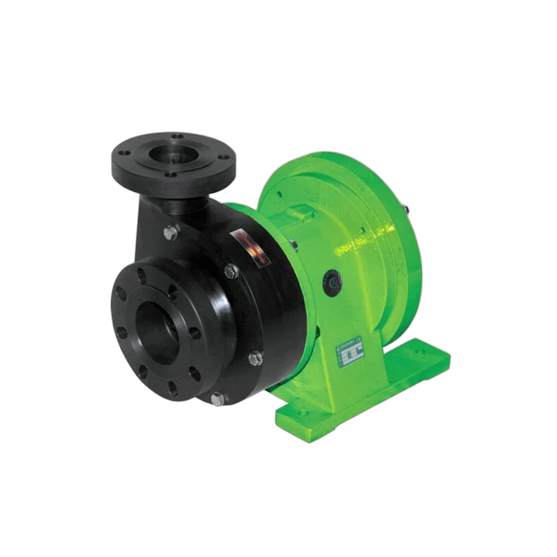
When investigating a pump failure, the source of the problem is often not the pump itself, but the suction line. Even a properly selected pump will experience cavitation in an improperly installed suction line; the impeller will melt, and the bearings and mechanical seal will fail prematurely.
In this guide, we discuss the physics of cavitation, NPSH calculations, and practical ways to improve the suction line, using numerical examples.
If you are currently experiencing an issue with the suction line, you can go directly to the diagnostic chart, which also distinguishes conditions that resemble cavitation but are not cavitation.
What is cavitation?
Every liquid has a vapor pressure at every temperature. If the pressure of the liquid drops below this value, the liquid boils—even if its temperature does not increase. Water boils at 20 °C when its pressure drops to approximately 23 mbar.
The pressure at the pump suction reaches its lowest value at the impeller inlet. If the pressure drops below the vapor pressure at this point, vapor bubbles form. When the bubbles are carried into the region of the impeller where the pressure rises, they collapse suddenly (implosion). The micro-jets formed at the collapse point generate very high local pressures and dislodge particles from the metal surface.
Symptoms of cavitation:
NPSHa and NPSHr
Basic rule: NPSHa must be greater than NPSHr—and the difference should include a safety margin.
Why isn't the same margin enough for every pump?
NPSHr alone does not indicate how susceptible a pump is to cavitation. Of two pumps with the same NPSHr value, one may sustain damage much more quickly than the other once cavitation begins. The decisive factor is suction energy: the peripheral speed at the impeller inlet, the impeller eye diameter, the suction specific speed, and the pump’s length collectively determine the energy released when a bubble collapses.
For this reason, the Hydraulic Institute’s ANSI/HI 9.6.1 guideline does not specify the margin as a single number, but rather provides it based on the application class and suction head; it also takes into account factors such as material, operating conditions, and changes in NPSHa over time. In practical terms, this means that while a 0.5 m margin may be insufficient for a high-speed, large-diameter pump with high suction energy, the same margin can operate without issues in a small, low-speed pump.
How is NPSHa calculated?
In meters of liquid column:
NPSHa = (Pa − Pv) ÷ (ρ × g) ± hs − hf
Example 1 — 20 °C water, 2 m suction lift
Open tank at sea level; pump 2 m above the liquid level; suction line losses of 0.8 m.
If the pump's NPSHr value at this flow rate is, for example, 3.5 m, the margin is sufficient.
Example 2 — The same system, but with the fluid at 80 °C
The only variable is temperature:
Same system, same pump—but the NPSHa dropped from 7.31 m to 2.86 m. With an NPSHr of 3.5 m, the pump will now experience cavitation. This is why suction lift is not used with hot liquids, and why the tank is positioned higher than the pump.
Example 3 — The same hot liquid, but with flooded suction
The way to save the 80 °C line in Example 2 is not to replace the pump, but to change the configuration. Let’s place the pump 3 m below the tank; since the suction line will be shorter, the head loss will also decrease to 0.5 m:
The pump, which has an NPSHr of 3.5 m, now operates with a margin of 4.66 m. The only factors that have changed are the pump’s elevation and the length of the line. When dealing with hot fluids, the question is not “which pump,” but “where the pump should be installed.”
What changes in closed, pressurized tanks?
In the formula, Pa represents atmospheric pressure in an open tank; in a closed tank, it represents the absolute pressure inside the tank. There are two common mistakes made here. The first is forgetting to add atmospheric pressure to the gauge pressure indicated by the manometer—the calculation is performed using absolute pressure. The second is more insidious: in closed tanks containing a liquid at its boiling point (liquefied gas, condensate tank, column under vacuum), the tank pressure equals the vapor pressure; the two terms cancel out, and NPSHa reduces to simply the static head minus the losses. In such cases, suction lift is mathematically impossible.
| Water temperature | Vapor pressure | Net load provided by the atmosphere (sea level) |
|---|---|---|
| 20 °C | 2,340 Pa | 10.11 m |
| 40 °C | 7,380 Pa | 9.65 m |
| 60 °C | 19,940 Pa | 8.44 m |
| 80 °C | 47,390 Pa | 5.66 m |
| 100 °C | 101,325 Pa | 0 m — flooded suction required |
Altitude is also a factor
Atmospheric pressure decreases with altitude; in Turkey, this creates a significant difference. For water at 20 °C in an open tank:
| Altitude | Atmospheric pressure | Net load (20 °C water) |
|---|---|---|
| 0 m (Istanbul, Izmir) | ≈ 1013 mbar | 10.11 m |
| 900 m (Ankara) | ≈ 910 mbar | 9.05 m |
| 1,900 m (Erzurum) | ≈ 805 mbar | 7.98 m |
A plumbing system design that operates without issues at sea level will lose nearly 2 meters of NPSHa when implemented in a high-altitude area. This adjustment must be made when replicating the design.
hf — Don't estimate suction loss; calculate it
The term most often estimated by eye in NPSHa calculations is friction loss. In fact, the calculation is simple and consists of two components: straight-pipe loss and fitting loss (elbows, valves, strainers, check valves, reducers).
A common method is the equivalent length approach: each additional section is converted to the length of a straight pipe that produces the same loss; the total length is calculated and multiplied by the value read from the pipe manufacturer’s loss table (m/100 m). Three points are sufficient for a rough verification:
How much margin should you leave?
NPSHr is generally defined in manufacturer tests as the point at which the head drops by 3%. In other words, when NPSHa = NPSHr, the pump is not “free from cavitation”; this is the point at which measurable performance loss begins. Therefore, a margin is essential.
The Hydraulic Institute's ANSI/HI 9.6.1 guideline specifies the margin as the NPSHa ÷ NPSHr ratio and adjusts it according to the application:
General rule of thumb: a minimum absolute margin of 1.0 m or a ratio of 1.1—whichever is greater. For critical services, the higher ratios recommended by the standard should be applied.
Calculate based on the worst-case scenario: when the tank is at its lowest level, the fluid is at its hottest, the filter is at its dirtiest, and the pump is operating at its highest flow rate.
How can NPSHa be increased?
Each term in the formula is an intervention point:
| Method | Effect | Note |
|---|---|---|
| Raise the liquid level / lower the pump | Most effective — hs increases directly | Flooded suction is the ideal configuration |
| Increase the suction pipe diameter | hf decreases significantly | Select a suction pipe larger than the discharge pipe |
| Shortening the suction line and reducing the number of elbows | hf decreases | Move the pump closer to the tank |
| Clean the strainer/filter | hf drops | A clogged strainer is the most commonly overlooked cause |
| Cool the liquid | Pv drops — this has a significant effect | Look at the difference in Example 2 |
| Pressurizing the tank | Pa increases | Applicable in closed systems |
| Pump with lower NPSHr / low speed | NPSHr decreases | Reducing speed significantly reduces NPSHr |
Not cavitation, but two issues that produce the same sound
Not every noise on the suction side is caused by cavitation. If the NPSH calculation is correct but the pump is still making noise and the flow rate is fluctuating, the cause is most likely one of the following two:
1. Air intake from the line
The suction line operates below atmospheric pressure; therefore, a leak there does not result in an outward leak but rather draws air into the system, making it imperceptible to the naked eye. Typical entry points include: loose flange gaskets, valve stem packing, gear connections, and the pump’s own mechanical seal. The symptoms resemble those of cavitation—noise, vibration, and reduced flow rate—but increasing the NPSHa will not resolve the issue. To verify: pressurize the line and perform a sealing test.
2. Vortex and Insufficient Diving Depth
If the liquid level in the tank or suction chamber gets too close to the suction inlet, a vortex forms at the surface and air is drawn directly into the pipe. This is called insufficient submergence, and it begins suddenly as the level drops—this is the cause of most malfunctions described as the pump “failing when the tank is half empty.”
The situation with other pump types
From Symptom to Cause: Diagnosing Suction Line Issues
| Symptom | Possible cause | Initial Check |
|---|---|---|
| A sound like gravel rattling, vibration | Cavitation | NPSHa calculation: temperature, level, strainer, altitude |
| There is noise, but the NPSHa calculation comes out comfortably | Air ingress from the suction line | Flange gaskets, valve stem, mechanical seal; sealing test |
| Noise and flow rate fluctuations begin when the tank is half empty | Vortex — insufficient submergence depth | Lowest level, vortex breaker, suction diameter |
| Flow rate decreased over time; noise began later | Strainer/filter clogging | Suction strainer differential pressure |
| Noise during commissioning with hot fluid | Decrease in NPSHa with temperature | Vapor pressure at operating temperature; transition to flooded suction |
| Spongy wear at the impeller inlet edge | Prolonged cavitation | Re-evaluate the margin according to ANSI/HI 9.6.1 |
| Mechanical seals and bearings fail repeatedly | Cavitation/air-induced vibration | Suction side; alignment and vibration measurement |
| Noise begins when flow rate increases | NPSHr increases with flow rate; the margin has been exhausted | Move the duty point back along the curve |
Suction Line Checklist
Frequently Asked Questions
What is the difference between NPSHa and NPSHr?
NPSHr is a pump characteristic; it is read from the manufacturer’s curve and increases with flow rate. NPSHa is a system characteristic; you calculate it. NPSHa must always be greater than NPSHr, and the difference between them should provide a margin appropriate for the application class.
If NPSHa equals NPSHr, won't the pump experience cavitation?
It does. NPSHr is generally defined as the point at which the head drops by 3%; in other words, at that value, cavitation has already begun and there is a measurable loss of performance. The point at which cavitation has not yet begun corresponds to a higher NPSH value. A margin is therefore essential.
Can I adjust the flow rate by turning down the suction valve?
No. Throttling the suction directly reduces the NPSHa and causes cavitation. The flow rate is throttled by the discharge or adjusted by reducing the speed.
Does altitude really make a difference?
That's correct. Since atmospheric pressure decreases with altitude, a project operating at sea level could lose nearly two meters of NPSHa at a high-altitude site. This adjustment must be made when replicating the same project at a different site.
I can hear cavitation, but I can't replace the pump. What can I do?
First, check the system side: clean the strainer, increase the suction pipe diameter, shorten the suction line, cool the fluid, raise the tank level, or lower the pump. These measures are often both less expensive and more permanent than replacing the pump. If all system-side options have been exhausted, reducing the speed will significantly lower the NPSHr.
If you provide your pumping conditions (fluid, temperature, altitude, tank configuration, line length), we can evaluate the appropriate pump along with its NPSH margin—get in touch with us.