

In a conventional centrifugal pump the shaft passes through the casing, and that penetration is sealed with a mechanical seal. The seal is the pump’s most failure-prone component and its only leak path. When the liquid is an acid, a solvent, a flammable or a toxic product, that leak is not merely a maintenance item; it is a safety, environmental and emissions problem.
A magnetic coupling pump removes the problem at its root: the shaft never penetrates the casing. Power is transmitted magnetically, through a closed vessel. The result is a pump with no leak path at all — a sealless pump.
Removing the seal, however, does not remove the possibility of failure — it relocates it. Selected or operated incorrectly, a magnetic drive pump presents a different set of failures: decoupling, an overheating containment shell, a bearing that cracks within seconds, a rotor that loses its magnetism for good. This guide covers what you need to know both to select the right model and to avoid losing the pump in its first year. If you already have a problem in the field, start from the fault diagnosis table below.
How does a magnetic coupling work?
The system has three parts:
- Outer rotor (drive magnet): Mounted on the motor shaft, rotating in atmosphere.
- Containment shell (can): A single-piece, unpierced vessel that separates the liquid volume from the atmosphere. This is the source of the leak-free design; standards call it the primary containment, and it is closed only by static elements such as gaskets and O-rings — there is no moving sealing face.
- Inner rotor (driven magnet): Attached to the impeller and rotating inside the liquid.
When the outer rotor turns, its magnetic field passes through the containment shell and drags the inner rotor with it. This is a synchronous coupling: under normal conditions the inner and outer rotors turn at exactly the same speed, with no slip.
There is a second flow inside the pump
The key to understanding a magnetic drive pump is a detail most datasheets leave out: a small part of the liquid you are pumping never leaves the pump. Pressure generated by the impeller directs a portion of the flow into the rear of the pump — the narrow annulus between the inner rotor and the containment shell. This internal circulation flow does three jobs at once:
- It lubricates the bearings. The inner rotor turns on plain bearings lubricated by the pumped liquid itself; there is no other lubricant.
- It cools the containment shell. It carries away both the heat generated by eddy currents and the friction heat of the rotor moving through the liquid.
- It keeps the liquid liquid. As the temperature rises in that narrow gap, the pressure must stay above the vapour pressure — otherwise the liquid boils right there.
Most magnetic drive pump failures originate exactly here: this internal flow is interrupted or allowed to overheat. Dry running, operating against a closed valve, running at very low flow for extended periods and cavitation all attack the same place — the liquid in that gap. The rest of this guide works through the links in that chain one by one.
Concept 1 — Decoupling
The torque a magnetic coupling can transmit is limited. If the load exceeds that limit, the magnetic bond breaks: the outer rotor keeps turning while the inner rotor stalls or turns erratically. This is called decoupling.
This is not just a loss of performance. When the bond breaks, magnetic energy is converted into heat and the containment shell and magnets heat up rapidly. At the same time the internal circulation flow stops — cooling is cut off at precisely the moment it is needed most. If the condition persists, the magnets can be permanently demagnetised and the coupling rendered useless. It is one of the most expensive failure modes in magnetic drive pumps.
Typical causes of decoupling:
- Pumping a liquid denser or more viscous than expected (torque rises directly with density).
- Starting up with a liquid whose viscosity has risen in the cold. This is the classic cause of first-start-of-the-morning failures in winter.
- The impeller jamming on a solid object.
- Sudden valve closure, or operating far out on the curve at excessive flow.
- Direct-on-line motor starting — starting torque can be a multiple of running torque.
For this reason the specific gravity limit must always be checked during selection. The datasheet for the GPM Caster M thermoplastic series, for example, gives this limit as 2 kg/dm³. That is safe for liquids up to twice the density of water; if you are planning a heavier solution, the model must be selected from the next torque class up.
A point that is often missed in practice: torque demand rises with density and viscosity, while the coupling’s capacity falls with temperature. A selection made for a hot line without accounting for magnet temperature leaves a narrower margin than it appears to — a subject we cover in Concept 4.
Protection: A relay monitoring motor current or power can detect decoupling within seconds and stop the pump. On critical services this should be treated as standard; a temperature sensor on the containment shell catches the same event from the heat side.
Concept 2 — Eddy current losses
If the containment shell is made from an electrically conductive metal (stainless steel, Hastelloy and similar), the rotating magnetic field induces eddy currents within it. These currents have two consequences: energy loss and heating. The loss goes straight into the liquid as heat.
Eddy current loss increases with the shell’s conductivity, diameter, wall thickness and rotational speed, so it becomes pronounced in high-speed and large-diameter couplings. With a non-conductive shell (composite, ceramic, PEEK) this loss disappears in practice.
| Containment shell | Eddy current loss | Advantage | Watch out for |
|---|---|---|---|
| Metallic (stainless, Hastelloy) | Present — produces heat and efficiency loss | Withstands high pressure and temperature; mechanically robust | Adds heat to the liquid; the liquid can overheat at low flow |
| Non-metallic (composite, ceramic, PEEK) | Practically none | Higher efficiency, no heating issue | Lower pressure/temperature limits; sensitive to impact |
One correction is worth making here: eddy currents are not the only loss in a magnetic drive pump. The viscous friction loss of the inner rotor turning in the liquid is also a significant share, and it does not disappear when the shell is non-conductive. Moving from a metallic to a non-metallic shell improves efficiency; it does not make the pump lossless.
Both losses end up in the same place: the liquid in the containment shell. Hence the practical rule — do not run at low flow for long periods. That liquid is the only coolant available. If flow falls too far, particularly on metallic-shell models, the liquid heats up, may vaporise, and bearing lubrication breaks down. This is why manufacturers publish a minimum continuous flow; on some models even “just a minute” against a closed discharge valve is enough to cost a bearing.
On lines where flow varies widely, the answer is not to select the pump for the lowest point; it is to guarantee minimum flow with a by-pass line or a variable frequency drive.
Concept 3 — Dry running: the most common cause of damage
The inner rotor of a magnetic drive pump turns on plain bearings lubricated by the pumped liquid itself. These bearings are usually silicon carbide (SiC).
SiC is extremely wear-resistant and, as long as it is lubricated by liquid, extremely long-lived. But it is brittle and sensitive to thermal shock. If the pump runs dry, lubrication and cooling are lost simultaneously; frictional heat can crack the bearing within seconds. Carbon-graphite bearings are more forgiving of dry running but have lower wear resistance, and their life is shorter in abrasive liquids.
It is important not to misjudge the timescale here: this is a matter of seconds, not minutes. “It ran dry but we shut it down straight away” usually means the bearing had already cracked. Nor is the damage always immediately visible — a cracked bearing may keep running for a while and then break up without warning.
Practices that prevent dry running:
- Fit a low-level switch on the suction tank and interlock the pump.
- Always fill the pump with liquid before start-up (priming); magnetic drive pumps are not self-priming.
- Never run with the suction valve closed.
- On tank-emptying duties, interlock the end of the run to an automatic stop — this is where magnetic drive pumps most often run dry.
- Use a power monitoring relay: it catches both dry running and decoupling.
Cavitation is a similar threat to the bearings: the vapour bubbles it produces break the lubricating film. For suction line design and NPSH calculations, see our NPSH and cavitation guide.
Concept 4 — Magnet temperature and permanent loss of torque
Magnetic drive pump datasheets usually give a single “maximum liquid temperature” without explaining where the number comes from. The answer is generally not the casing material but the magnet itself.
Permanent magnets weaken as they heat up, in two distinct ways:
- Reversible loss: Magnetic strength falls as temperature rises and returns when it cools. The torque a coupling can transmit on a hot line is lower than the room-temperature catalogue figure.
- Irreversible loss (demagnetisation): If the material’s maximum operating temperature is exceeded, part of the magnetic strength is lost for good. Even after the pump cools it does not regain its original torque, and decoupling becomes a recurring event.
Two magnet families are used in industry, and the difference between them is decisive on hot services:
| Neodymium (NdFeB) | Samarium-cobalt (SmCo) | |
|---|---|---|
| Magnetic strength (remanence) | Higher — 1.0–1.4 T | Lower — 0.8–1.16 T |
| Curie temperature | 310–400 °C | 700–800 °C |
| Maximum operating temperature | ~80 °C for standard grades; up to 230 °C for high-temperature grades | 250 °C and above |
| Strength loss with temperature | Faster (approx. −0.09…−0.12 %/K) | Slower (approx. −0.03…−0.05 %/K) |
| Corrosion | Susceptible; requires plating | Resistant; usually needs no coating |
The third row from the bottom is the important one. A coupling with standard neodymium magnets is at its limit at around 80 °C — yet plenty of process lines run at that temperature. Hot services therefore use either high-temperature grade neodymium or samarium-cobalt; because SmCo is weaker, the coupling has to grow to deliver the same torque, and the cost rises with it. That is usually the answer to “why is the hot version so much more expensive?”
One caution: the temperature the magnet sees is higher than the line temperature. Eddy current and friction losses heat the liquid in the containment shell, and the inner rotor sits in that heated liquid. If you are working close to the limit, ask the manufacturer to confirm the magnet temperature, not the liquid temperature. For services that genuinely require high temperature and high pressure there is a separate metallic-cased product family such as the GPCA / GPTA series; pushing a thermoplastic model past its temperature limit is not a solution.
Ferrous particles: the silent enemy
The least known weakness of a magnetic drive pump is hidden in its name. The inner rotor is a powerful magnet, and it attracts ferrous particles out of the liquid. Rust scale, weld slag, machining swarf, sediment lifted off a tank bottom — all of it collects in the narrow gap between the rotor and the containment shell. That gap is on the order of a millimetre; debris there starts a damage chain that runs from friction and wear all the way to a perforated shell.
The problem is worst at two points:
- First commissioning of a new installation. Swarf and slag left over from pipework fabrication arrive at the pump on the first run. This is the single riskiest moment in a magnetic drive pump’s life.
- Tank-bottom stripping and solids dissolution duties. Trace iron in powdered raw material accumulates significantly over time.
The countermeasures are simple and inexpensive: flush the line before commissioning, fit a suitably sized strainer on the suction, and keep it cleanable. A standard Y-strainer separates by size only and will not retain micron-scale iron dust; where that risk is high, a magnetic trap on the suction side is the right answer. For liquids carrying abrasive solids a magnetic drive pump is the wrong choice to begin with — look at an air-operated double-diaphragm pump instead.
Thermoplastic or metallic?
Magnetic drive pumps are offered in two main casing families, and the choice follows the chemistry and the operating conditions.
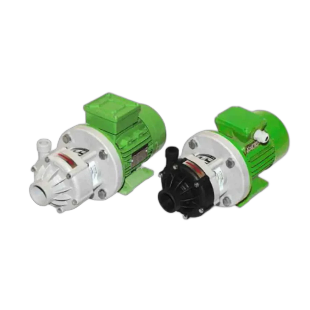
- Thermoplastic (PP / PVDF): Superior to metal in acids, alkalis and salt solutions. Because it is a bulk material rather than a surface coating, corrosion cannot “eat through” it. Temperature and pressure limits are lower. The GPM Caster M datasheet gives, for PVDF, a temperature range of −10 … +90 °C, a system pressure of 4 bar, a capacity of 30 m³/h and a head of 25 m at 50 Hz.
- Metallic (316, Alloy 20, Hastelloy): For high temperature, high pressure and solvents. Hot oil, heat transfer fluids and high-temperature processes belong to this family. Solvents can also swell thermoplastics, which is a further reason to choose metal.
A common mistake is to look only at the casing. Four separate materials contact the liquid and each must be compatible on its own: the casing, the containment shell, the bearings (SiC or carbon) and the static seals (PTFE, FKM, EPDM). If one of them is incompatible the pump does not stop being leak-free — but its life is shortened. For matching materials to your liquid, see our chemical compatibility guide and the chemical compatibility chart.
Magnetic drive or canned motor?
There are two families of sealless pump, and they frequently appear side by side when quotations are compared. A magnetic drive pump (MDP) has a standard electric motor and a separate coupling. In a canned motor pump (CMP) the motor rotor is attached directly to the impeller and the stator winding is itself enclosed in a can — motor and pump are a single unit.
| Magnetic drive (MDP) | Canned motor (CMP) | |
|---|---|---|
| Motor | Standard motor — any brand or efficiency class | Pump-specific motor; not separately available |
| Repair | Can be done on site | Usually returned to the manufacturer or an approved shop |
| Footprint and noise | Longer; fan and coupling noise present | Compact and quiet |
| Spare parts | Widely available | Limited |
| Initial cost | Generally lower | Generally higher |
The practical distinction: plants that want to maintain the pump with their own team and keep flexibility on the motor side choose magnetic drive, while critical services dominated by space constraints, noise limits and maximum containment safety tend towards canned motor. Both types fall under the same standards (ISO 15783, API 685).
What the standards actually tell you
The standards that appear on magnetic drive pump datasheets mean the following in practice:
- ISO 2858 / DIN 24256: The dimensional standard for end-suction centrifugal pumps (connection sizes, baseplate holes, nominal duty points; 16 bar rating). What it means: pumps of the same frame size from different manufacturers are interchangeable without modifying the pipework.
- ISO 5199: The technical specification for the same pumps; it defines reliability criteria such as shaft deflection, bearing life and vibration. Widely specified in the chemical and petrochemical industries.
- ISO 15783: The standard written specifically for sealless pumps — covering both magnetic drive and canned motor types. It defines design requirements relating to installation, maintenance and operational safety for chemical, water treatment and petrochemical service, and the items to be agreed between purchaser and manufacturer. If you are writing a magnetic drive pump specification, this is the document to start from.
- API 685: The sealless centrifugal pump standard for the petroleum, petrochemical and gas industries — the most demanding service class. Its 3rd edition (2022) clarified the definitions of secondary containment and how it is to be achieved: a second barrier to retain the liquid should the containment shell fail, together with the associated instrumentation. This is what is called for on critical and hazardous duties.
You can review the options, including centrifugal models covered by ISO 5199 / ISO 2858 / DIN 24256 / API 685, in our magnetic pumps category.
ATEX and explosive atmospheres
On lines carrying flammable solvents, alcohols or fuels the pump usually sits in a zone classified as an explosive atmosphere. In the European Union such equipment falls under Directive 2014/34/EU (ATEX); in Türkiye the equivalent is the harmonised regulation on equipment and protective systems intended for use in potentially explosive atmospheres.
Three things are checked in practice:
- Zone: For gases and vapours, Zone 0 (continuous), 1 (occasional), 2 (rare and short-lived). The equipment category must match the zone.
- Gas group: IIA (propane), IIB (ethylene), IIC (hydrogen, acetylene — the most severe). Equipment marked IIC may also be used in IIB and IIA; the reverse is not true.
- Temperature class: The maximum surface temperature of the equipment must stay below the ignition temperature of the gas present. The classes are T1 = 450 °C, T2 = 300 °C, T3 = 200 °C, T4 = 135 °C, T5 = 100 °C, T6 = 85 °C.
Temperature class matters particularly in a magnetic drive pump, because eddy current and friction losses heat the containment shell, and that heating becomes very rapid in the event of dry running or decoupling. For an ATEX-rated magnetic drive pump, therefore, dry-run and decoupling protection is not an optional accessory but a safety requirement. An ATEX certificate on the motor alone is not sufficient; the pump end must be marked as well.
Types of magnetic drive pump
Magnetic couplings are not exclusive to centrifugal pumps; they are combined with several hydraulic types:
- Centrifugal: High flow, low to medium head. The default choice for general chemical transfer.
- Regenerative turbine: Low flow with high head. Preferred for low-viscosity liquids close to their boiling point (liquefied gases, solvents); doing the same job with a centrifugal pump would require a far larger machine.
- Gear (magnetically driven): A positive displacement, leak-free solution for viscous liquids. See our viscous fluid transfer guide on this subject.
- Vane (positive displacement): For services requiring constant flow with low-viscosity liquids.
When magnetic drive, when a sealed pump?
| Situation | Recommendation |
|---|---|
| Toxic, flammable, volatile (VOC) or carcinogenic liquid | Magnetic drive — no leak path |
| Valuable or expensive product (losses are costly) | Magnetic drive |
| ATEX zone, fugitive emission limits | Magnetic drive |
| Frequent and expensive seal maintenance | Magnetic drive — lower total cost of ownership |
| Slurry containing abrasive solids | Sealed pump or an AODD pump — solids abrade the internal bearings |
| Line with a frequent risk of running dry | Sealed or diaphragm pump; if magnetic drive is chosen, protection is essential |
| Line where flow varies frequently and widely | If magnetic drive is chosen, secure the minimum flow (by-pass / VFD) |
| Very high viscosity | Positive displacement pump (gear / progressing cavity) |
The initial cost of a magnetic drive pump is higher than a sealed equivalent. In return, seal replacement, downtime, product loss and leak clean-up disappear from the budget; on services where leakage is unacceptable, the difference is recovered quickly. When making the comparison, count not only the price of the seal itself but the production downtime during replacement and the cost of any auxiliary system (barrier fluid, seal support plan).
Symptom to cause: quick fault diagnosis
Most symptoms seen in the field trace back to one of the four concepts above:
| Symptom | Likely cause | First check |
|---|---|---|
| Motor turns, no flow, humming from the pump | Decoupling | Liquid density/viscosity, impeller jam, motor current |
| A “snap” at start-up, then loss of flow | Starting torque exceeded on a cold liquid | Viscosity at start-up temperature |
| Containment shell overheating | Low-flow operation or blocked internal circulation | Minimum flow, strainer, by-pass line |
| Sudden seizure while running | Bearing (SiC) fracture | History of dry running, level switch |
| Vibration and noise increasing over time | Bearing wear or debris in the rotor gap | Solids, ferrous particles, strainer condition |
| Reduced head, frequent decoupling | Permanent loss of magnet strength | Past overheating events, liquid temperature |
| Intermittent flow, crackling noise | Cavitation | NPSH calculation, suction strainer, tank level |
This table is a first-pass screening tool; a definitive diagnosis requires stripping the pump and visually inspecting the bearing and containment shell surfaces. Discolouration and cracks on the bearing face indicate dry running; scoring on the inner surface of the shell points to debris or rotor contact.
Selection checklist
- Liquid name, concentration, operating temperature and specific gravity (critical for the torque limit).
- Viscosity — including its value at the lowest ambient temperature (start-up is the riskiest moment).
- Any solids? If abrasive solids or ferrous particles are a risk, a magnetic drive pump may not be the right choice.
- Duty point (flow + head), system pressure and minimum continuous flow.
- The four wetted materials: casing, containment shell, bearings, static seals. If a metallic shell is chosen, allow for the heat it adds.
- Magnet temperature class — get confirmation from the manufacturer on hot lines.
- Dry-run and decoupling protection (level switch + power monitoring; treat as mandatory in an ATEX zone).
- Suction line NPSH calculation and priming arrangement.
- Commissioning plan: line flushing, strainer, supervision on first start.
Frequently asked questions
Can a magnetic drive pump run dry?
No. Because the bearings are lubricated by the pumped liquid, dry running causes damage within seconds. Some bearing materials (carbon-graphite) tolerate it better, but they buy time rather than provide a solution. On lines with a high risk of running dry, either work with level protection or choose a type that can run dry, such as an air-operated double-diaphragm pump.
Is a magnetic drive pump self-priming?
Standard centrifugal magnetic drive pumps are not self-priming; they must be filled with liquid before start-up. Where suction lift is required, either install the pump below the liquid level or consider a self-priming type.
Why is a magnetic drive pump more expensive than a sealed one?
Most of the cost comes from the permanent magnets and the manufacture of the containment shell. Against that, seal replacement, barrier fluid systems, downtime and product loss from leakage all disappear. On services where leakage is unacceptable, the difference is recovered within the first few seal changes.
Can a magnetic drive pump handle solids?
Only to a very limited extent. Soft, low-concentration solids are accepted on some models; abrasive solids and especially ferrous particles are not. Ferrous particles stick to the magnet and accumulate in the rotor gap.
What happens if the containment shell fails?
Liquid passes into the outer rotor area. On a standard pump that means a leak, which is why critical services under API 685 call for secondary containment and leak detection instrumentation. On hazardous liquids this feature needs to be written into the specification.
Can it be run on a variable frequency drive?
Yes, and it is usually beneficial — soft starting reduces the risk of decoupling. But reducing speed also reduces flow, and the minimum continuous flow must not be breached. It is worth confirming that lower limit with the manufacturer.
You can review thermoplastic and metallic magnetic coupling pump options in our magnetic pumps category. Share the name, temperature, density and duty point of your liquid and get in touch — we will put together a model recommendation along with the appropriate casing, bearing and protection options.