


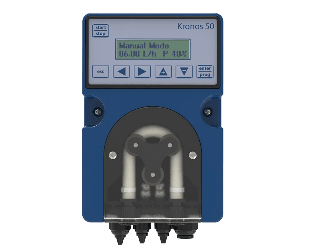
A dosing pump is used not to transport a liquid, but to dispense it in a measured and repeatable manner. In water treatment, chlorine and coagulants; in boiler rooms, corrosion inhibitors; in the food industry, pH regulators; and in swimming pools, disinfectants—all are dispensed using dosing pumps. Since the expectations for accuracy are high, the choice of technology is much more critical than for transfer pumps.
In this guide, we compare three main technologies—solenoid (electromagnetic) diaphragm, motor-driven mechanical diaphragm, and peristaltic—; we discuss what accuracy means, the two issues that cause the most problems in the field (back pressure and gas leakage), and how the line should be installed. If you’re experiencing problems with an operational line, you can refer to the troubleshooting table.
Three technologies, three different operating principles
Solenoid (electromagnetic) diaphragm-type
An electromagnet pushes the diaphragm in a pulsating motion along with the piston to which it is attached; the spring pulls it back. Each pulse displaces a fixed volume; the flow rate is adjusted by the pulse frequency (strokes per minute) and stroke length.
Among the solenoid dosing pumps we offer, the Seko Tekna and Kompact series fall into this category; the Tekna ATEX option is available for sites requiring ATEX compliance.
Motor-driven mechanical diaphragm
The electric motor mechanically moves the diaphragm via an eccentric shaft or crankshaft. The reciprocating motion is stronger and more stable than that produced by a solenoid.
Our line of mechanical dosing pumps includes the Spring, Kosmo, and Digital Elektra series; for heavier-duty applications, we offer the Invikta series.
A higher-class variant of this family is the hydraulic diaphragm pump: the diaphragm is not actuated by a mechanical lever, but rather by oil pressurized by a piston. Since the diaphragm is subjected to pressure from both sides, it does not experience mechanical stress; this allows for very high pressures and extends the diaphragm’s service life. This is the type sought after in petrochemical and high-pressure process lines.
Peristaltic (tube) pump
The fluid is contained solely within the hose; the rotating rollers squeeze the hose to force the fluid through. No mechanical parts of the pump come into contact with the fluid.
Our line of peristaltic dosing pumps includes the Kronos series, featuring the PR, PM, PTS, and PRT models.
The only factor that needs to be planned for in peristaltic pumps is hose life, and this life is determined not by a schedule but by the number of compressions. Operating the pump at a low speed (selecting a larger size and reducing the speed if necessary) directly extends hose life. Other factors that shorten service life include high pressure, high temperature, and chemicals that cause the hose to swell. On critical lines, the hose is replaced on a scheduled basis before it bursts; many models feature a leak detector that alerts the operator to a hose rupture.
Comparison Table
| Specification | Solenoid-diaphragm | Motor-driven mechanical diaphragm | Peristaltic |
|---|---|---|---|
| Typical flow rate range | Very low – medium | Medium – high | Very low – medium |
| Back pressure capacity | Medium | High | Low – medium |
| Gas-releasing liquid (e.g., hypochlorite) | Weak (degassing valve required) | Medium | Very good |
| Viscous liquid | Weak | Good | Very good |
| Liquid containing solids/precipitate | Poor | Weak | Very good |
| Dry running | Limited | Limited | Problem-free |
| Consumables | Diaphragm, valve balls | Diaphragm, valves | Hose (regular replacement) |
| Initial investment | Low | High | Medium |
What does "accuracy" mean? Definitions of terms in the catalog
Dosing pump catalogs use terms that sound similar but refer to different things. Distinguishing between them is a prerequisite for comparing two quotes. API 675, the specification for positive displacement pumps used in the petroleum, chemical, and gas industries, defines these concepts and specifies that steady-state accuracy is ±1% across the entire turndown range.
API 675 covers heavy-duty process applications; this class of pump is not required for water treatment and pool applications. However, the definitions of the terms are the same for each class and provide a common language when comparing quotes.
Choosing the Right Flow Rate: The 20–80% Rule
The most common mistake with dosing pumps is buying a model that’s much too large, thinking, “I might need it later.” Dosing pumps operate most accurately within 20–80% of their capacity. Running a 100-liter-per-hour pump at 5% of its capacity significantly compromises accuracy: as the stroke length shortens, valve behavior and priming become unstable.
The right approach: Calculate your actual need and choose the model where that value falls within the pump’s mid-range.
Example: You want to add 2 ppm of chlorine to a line with a flow rate of 50 m³/hour, and you have a 10% sodium hypochlorite solution.
Hourly pure chlorine requirement: 50 m³/hour × 2 g/m³ = 100 g/hour.
%For a 10% solution: 100 g ÷ 0.10 = 1,000 g/hour ≈ 1 L/hour.
In this case, a pump with a capacity of 2–4 liters per hour is ideal; a 20-liter-per-hour model would reduce accuracy.
The general form of the equation is as follows, and it works the same way for every chemical:
Dosing flow rate (L/h) = [process flow rate (m³/h) × target dose (g/m³)] ÷ active ingredient concentration of the product (g/L)
Two points throw off the calculation. First, the label percentage of a commercial solution is not the same as the active ingredient concentration; using the percentage directly as g/L for products with a density other than 1 kg/L (such as acids and caustic soda) leads to errors. Second, products like hypochlorite degrade in storage: a dosage that is correct on the first day will result in an underdose a few weeks later. Therefore, dosing is not a task that can be set once and forgotten; measurement-based monitoring automatically corrects this deviation.
When calculating flow rate, include both the minimum and maximum requirements. The pump must meet 80% of the maximum requirement; the minimum requirement must not fall below 20%. If the difference between the two extremes exceeds the pump’s turndown ratio, a single pump will not suffice—either two pumps or a model with wider frequency/stroke control is required.
Back pressure and siphoning: two silent faults
The dosing pump operates on a volumetric basis; it dispenses a specific volume with each stroke. However, if the pressure balance in the system is disrupted, the dosing volume may deviate from the expected value.
A standard dosing line is typically set up in the following order: suction strainer and suction tube with level sensor → pump → pulse dampener (if necessary) → safety valve → back pressure valve → injection valve.
These two components are often misunderstood. The safety valve protects the line, and the discharge must return to the chemical tank—not to the floor. The injection valve, on the other hand, is not merely a connecting piece: the spring-loaded check valve inside it prevents the process fluid from flowing back into the dosing line, and the orifice at its tip ensures that the chemical is delivered into the center of the main flow. An injection against the pipe wall causes the chemical to concentrate there and corrode the pipe.
Suction line: a problem specific to reciprocating pumps
The flow from the dosing pump is not continuous but pulsating: during the suction stroke, the mass of fluid in the line is suddenly accelerated. In a long, narrow suction line, this acceleration causes an additional pressure loss, and the pump cannot complete its priming cycle even with a suction flow that appears sufficient on paper. The result is a dosing volume that is not detected during calibration but is insufficient during operation.
Practical measures are simple: keep the suction line short and wide at the pump inlet, minimize the number of elbows, position the tank above the pump if possible (to prevent flooded suction), and increase the suction diameter by one size when handling viscous fluids. For the equivalent principles in centrifugal pumps, please refer to our NPSH and cavitation guide.
Sodium hypochlorite: a classic case of "the pump isn't drawing water"
The most common complaint in water treatment and pool applications is that the pump stops pumping after a while during hypochlorite (bleach) dosing. The cause is not a pump malfunction: sodium hypochlorite decomposes over time and releases gas. The resulting bubbles accumulate in the valve seats of the diaphragm pump, preventing the valve from seating properly and causing the pump to lose suction (gas locking).
Applications that prevent this:
Material Compatibility and Calibration
The parts of the dosing pump that come into contact with the fluid are the pump head, diaphragm, valve balls and seating surfaces, O-rings, suction/discharge hoses, and the injection valve. The weakest link in the chain determines the pump’s service life.
| Chemical | Compatible head | Compatible elastomer | Note |
|---|---|---|---|
| Sodium hypochlorite | PVDF (preferred), PVC | FKM / PTFE | A degassing valve is recommended |
| Sulfuric acid (diluted) | PP, PVDF | PTFE / FKM | Behavior varies with concentration |
| Hydrochloric acid | PP, PVDF, PTFE | PTFE / FKM | 316 stainless steel is not suitable |
| Sodium hydroxide (20%) | PP, PTFE | EPDM / PTFE | Avoid PVDF in hot solutions |
| Polyelectrolyte / coagulant | PP, PVDF | EPDM / FKM | Viscous → peristaltic is preferable |
For detailed material specifications, please refer to our chemical compatibility guide; you can also look up the chemical you plan to transport directly in our compatibility table tool.
Calibration: The catalog flow rate is for reference only; the actual flow rate varies depending on the line pressure and the density of the fluid. Use a calibration cylinder during commissioning: have the pump draw fluid from the cylinder, measure the volume drawn over a specific time period, and adjust the settings accordingly. If this step is skipped, the dosing error can easily reach 20%.
There are three conditions for proper calibration: the measurement must be taken at the line’s actual operating pressure (measurements taken with the line drained are misleading), the pump must have been purged of air before the measurement, and the measurement must last at least a few minutes—calculations based on counting individual strokes will be inaccurate. Calibration is repeated when you fill the tank with a new chemical and after pump head maintenance.
Control and measurement: switching to closed-loop dosing
Constant-flow (open-loop) dosing with a fixed flow rate is sufficient where the load remains constant. If water quality varies, a closed-loop system is required: a probe measures the water quality, and the control panel sends a signal to the pump.
The most commonly overlooked aspect of a closed-loop system is dead time: the time it takes for the chemical to travel from the injection point to the probe. If the probe is placed too far away, the controller responds too late and the system begins to oscillate—the dosage fluctuates between too much and too little. The probe should be placed at a point where the mixture is fully blended but the delay remains minimal.
Our control and sensor product line includes the Control 40/42/65/100/102 and Control 800 panel series, as well as probes and calibration fluids. Regular calibration of the probes is the second requirement for dosing accuracy after the dosing pump: an uncalibrated probe sends incorrect commands to a properly functioning dosing pump.
Why is pH a determining factor in chlorine dosing?
It’s not enough to set up a closed-loop system; you need to understand why the target value is what it is. When it comes to chlorine dosing, the answer to this question lies in chemistry, and this is the source of the misunderstanding that causes the most financial losses in the field.
Chlorine exists in two forms in water: hypochlorous acid (HOCl) and the hypochlorite ion (OCl⁻). The equilibrium between the two is determined by pH; the dissociation constant (pKa) is 7.53. This means that at pH 7.53, they are present in equal proportions. As pH decreases, HOCl becomes dominant, and as pH increases, OCl⁻ becomes dominant:
| pH | HOCl | OCl⁻ |
|---|---|---|
| 6.53 | ≈ 91% | ≈ 9% |
| 7.53 | ≈ 50% | ≈ 50% |
| 8.53 | ≈ 9% | ≈ 91% |
The key point is this: HOCl is a significantly more potent disinfectant. Therefore, even if the "free chlorine" value you measure remains the same, the disinfecting power you achieve at pH 7 is not the same as that at pH 8.5. You use the same amount of chemical, but you do not get the same result.
This is also reflected in official thresholds. According to the World Health Organization’s guidelines for drinking water, effective disinfection requires a contact time of at least 30 minutes with a free chlorine concentration of ≥ 0.5 mg/L and a pH < 8.0; residual chlorine must be maintained throughout the distribution system, and free chlorine at the point of delivery must be at least 0.2 mg/L. The guideline value should normally not exceed 5 mg/L.
It is no coincidence that the condition pH < 8.0 appears alongside the threshold—it is a direct consequence of the equilibrium described above. The practical implication is clear: pH control is not an aid to chlorine dosing, but a prerequisite. In a system where pH is not controlled, the chlorine pump runs, chemicals are consumed, and the target residual appears to be achieved; but the disinfection capacity has silently declined.
ORP is not a measure of chlorine concentration
ORP (oxidation-reduction potential) is widely used and useful, but there is often confusion about what it measures: ORP measures the oxidizing potential of water, not the chlorine concentration.
This difference is important because it is primarily the HOCl concentration that determines the potential, and that concentration depends on the pH. Conclusion: In a system where the pH is not kept constant, the same ORP value may correspond to different free chlorine levels. Therefore, an ORP-based control loop is reliable only under two conditions:
- If the pH is also being monitored—otherwise, the reading will drift.
- If it has been correlated with a known free chlorine value at a constant pH—that is, if the ORP threshold has been calibrated once using a laboratory measurement.
An ORP threshold set without these two conditions being met is a number whose actual corresponding chlorine level is unknown.
How is free chlorine measured?
The determination of free and total chlorine in water is standardized by ISO 7393. The most common method used in routine testing is the DPD colorimetric method defined in ISO 7393-2: the density of the resulting red color is compared using a photometer or a calibrated color scale. In practice, the method is applicable in the range of approximately 0.03–5 mg/L.
An annex to the standard provides a procedure for distinguishing between the forms of bound chlorine: monochloramine, dichloramine, and nitrogen trichloride. This distinction is important in plant operations: if total chlorine appears high while free chlorine is low, it means the chlorine has combined with ammonia—there is residual chlorine, but the disinfecting power is below expectations.
Practical conclusion: The specification must state which parameter the control loop measures. The phrase “chlorine measurement” is not sufficient; it must specify whether it is free chlorine, total chlorine, or ORP. These three represent different parameters and cannot be controlled using the same setpoint.
Chemical Storage and Safety
The safety of the dosing line doesn't end with the pump; the tank side is just as important:
From Symptom to Cause: Rapid Troubleshooting
| Symptom | Possible cause | Initial Check |
|---|---|---|
| The pump is running, but the chemical isn’t flowing | Gas lock, valve not seating, air leak | Degassing valve, suction connection, valve balls |
| Dosage is lower than expected | Calibration is outdated, product has degraded, suction line is too long/narrow | Measurement using the calibration cylinder; product expiration date |
| Dosing is higher than expected; tank is emptying quickly | Siphoning | Back pressure valve, dosing point elevation |
| Dosing does not change proportionally when the flow rate is adjusted | Operating outside the linearity range (setting too low) | Adjust the setting to the 20–80% range; the model may be one size too small |
| The line is vibrating; connections are loosening | Pulse | Pulse damper and precharge pressure |
| Safety valve is opening frequently | The discharge line is clogged or the injection valve is closed | Injection valve, line blockage, crystallization |
| Diaphragm tears frequently | Excessive pressure, incompatible material, dry running | Operating pressure, material compatibility, level protection |
| The hose in the peristaltic pump bursts prematurely | High speed/pressure, chemical swelling | Reduce speed, review hose rating |
| Control panel is oscillating | Probe is too far away (dead time) or not calibrated | Probe position and calibration |
Quick Selection Summary
Frequently Asked Questions
What flow rate (in liters per hour) should be selected for the dosing pump?
Your peak demand should fall within the pump’s 80% range, and your minimum demand should be above 20%. Choosing a larger pump “just in case” reduces accuracy. If the difference between the two extremes exceeds the pump’s turndown ratio, a single pump will not suffice.
Is a back pressure valve required?
It is practically essential that the pressure at the dosing point be lower than the level in the chemical tank in every case—otherwise, the liquid will flow by siphoning even if the pump stops. It also maintains a stable dosing rate even at very low back pressure. It should not be confused with a safety valve; the two serve different functions and are often found together.
Which dosing pump is better for hypochlorite dosing?
If gas discharge is an issue, a peristaltic pump offers a structural advantage: since it has no valve, gas lock is not possible. If a diaphragm pump is preferred, a head with a degassing valve, a flooded suction port, and a combination of PVDF and FKM materials are required.
How often should the peristaltic tube be replaced?
It wears out based on the number of compression cycles, not the calendar; therefore, speed, pressure, and temperature determine its service life. Operating the pump at low speed extends its service life. Hoses on critical lines are replaced on a scheduled basis before they burst, and leak detectors are used.
When should I repeat the calibration?
When commissioning the system, when filling the chemical tank with a new product, after servicing the pump head or diaphragm, and when the line pressure changes. Periodic inspections are also required for products that degrade (such as hypochlorite).
If you provide the chemical’s name, concentration, target flow rate, and line pressure, we can work together to determine the appropriate model and material combination—get in touch or browse our dosing pumps category.